My second german Saturn for switchless MOD was not the same as the first one.
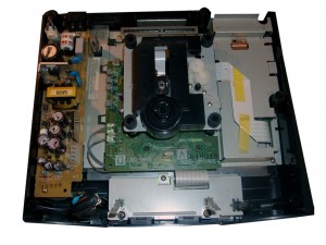
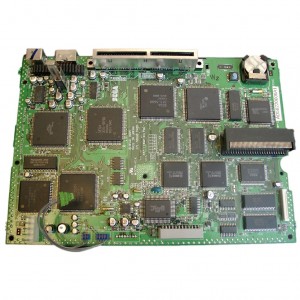
This one got 2 PCBs inside. A smaller Main PCB and a separate Controller Port PCB.
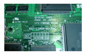
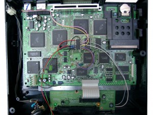
The Mainboard is called: 837-11892-01 PAL.
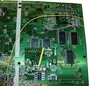
Here you can find the Mainboard Revision on the TOP Side of the Board
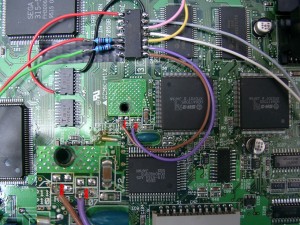
For correct working of the 50/60Hz you have to desolder Pin 1 and pull up pin 1 of IC20.
Then wire it to GND.
Backsite Mainboard.You need to cut the jumper at JP7 (remove the circuit)
Frontsite of the Mainboard (LED Resistors 220Ohm) PIC 16F630 cut the two red marked circuit pathes between JP12 and JP 10
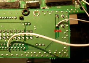
Separate Controller PCB (cut the red marked circuit)
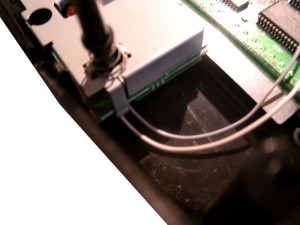
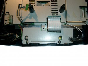
wire colors (upper site grey at the RESET Button, downsite white)
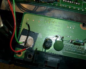
DUO-LED soldering an position at the separate Controller PCB
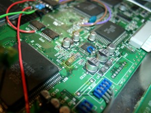
Some more pictures
