Inspired from petes fabulous site www.mmmonkey.co.uk and his switchless mods,
I want to make the ultimative Sega Genesis 2 switchless MOD including 32X and Sega CD2.
In the beginning we have to mod the Genesis 2 with the switchless mod, like I done before.
(Thanks to SEB for the great PIC Code).
Difference between standard Sega Genesis switchless mod
For making a 32X working you are in need of the pink wire. This signal is needed in the 32X.
We can make use of the A/V connector cable between the Genesis 2 and the 32X. The Mono Audio Signal is not in use, so we can cut the original Mono signal at the Genesis 2 A/V connector and the 32X A/V connector.
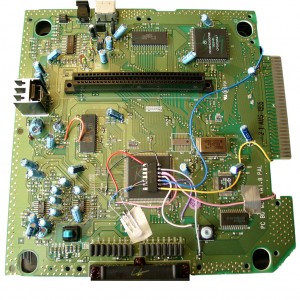
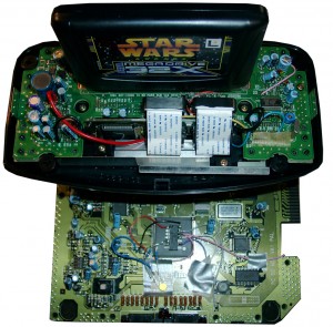
Here you will see the Sega Genesis 2 switchlees mod including the 3 more wires (yellow, blue, and pink).
The Pink is needed for the 32x.
Blue and yellow is needed if you want to make a Sega CD working too.
For 32X support add a 2nd pink wire to Pin 12 of the PIC.
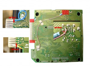
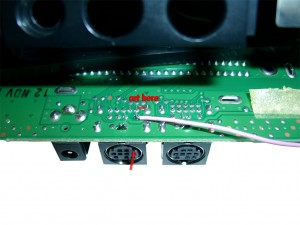
At the solder site you have to cut the cirquit path to Pin 6 of the A/V Port and solder the pink wire to Pin 6 of the A/V Port.
For Sega CD support you have to cut Pin A01 (yellow wire) and Pin A30 (blue wire) of the Genesis Expansionsport and solder the 2 wires to the PIC Pin 10 blue and PIC Pin 8 yellow.
Backsite of the Genesis 2:
Adding 32X support
First you have to open the 32X and remove the shielding.
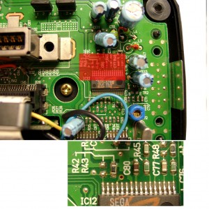
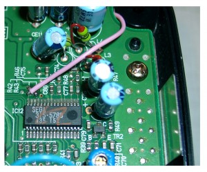
The only protection of the 32X is the 50/60Hz settings. You will find it at the right site of the mainboard IC12 SEGA 315-5788.
You will find R43, if its a PAL 32X (Pin 32 to GND) -> 50Hz
You will find R42, if its a NTSC 32X (Pin 32 to 5V) -> 60Hz
Remove the Resistor
Sega Genesis 2 A/V Pinout
|
Pin |
Description |
|
1 |
Blue |
|
2 |
+5V DC |
|
3 |
Green |
|
4 |
Composite Video |
|
5 |
Sync |
|
6 |
Audio Mono |
|
7 |
Red |
|
8 |
Audio Stereo L |
|
9 |
Audio Stereo R |
On the solder site you will have to Cut the cirquit path to Pin 6 of the A/V Port.
Solder one pink wire from AV Out Pin 6 (solder Site) to Pin 32 of IC12 (component site)
Adding Sega CD 2 support
You are in need of a Eprom (27c2004) and burn all 3 bios Version into it. The usa, japanese and pal Version. You can select the different Bios Version via A16 (Pin 38) and A17 (Pin 39) of the Eprom.
The order is: USA-> JPN -> EUR.
You can do it by yourself. Take the CD-Bios Versions and make a byteswap each of them.
The concat the 3 Files via Windows Commandline copy
copy /B usa.bin + pal.bin + jpn.bin switchless.bin
The final goal is to get 2 wires from the 16F630 PIC to the Eprom.
Here we make use of 2 wires from the Sega Expansionport.
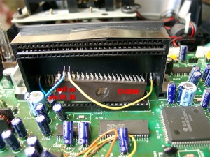
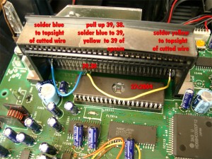
Pin8 yellow 16F630->Exp Port Pin A01@Genesis 2->Exp. Port Pin A30@SegaCD2->Pin 38Eprom
Pin 10 blue 16F630->Exp Port Pin A30@Genesis 2->Exp. Port Pin A30@SegaCD2->Pin 39Eprom
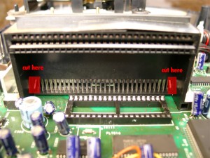
Pin A01 and A30 of the Expansionsport carrying GND. There are many ground Signals at the Expansionsport. So we can cut these two of and make use of the free Pins for the Bios select.
|
|
PIC 8 /Eprom 38 |
PIC 10 /Eprom 39 |
|
EUR |
0 |
1 |
|
JPN |
1 |
0 |
|
USA |
0 |
0 |
First you have to remove the original Bios:
cut the 2 wires left and right (A30, A01)
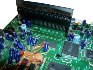
You will have to pullup Pin 38 and Pin 39 of the Eprom and wire blue and yellow like the following picture
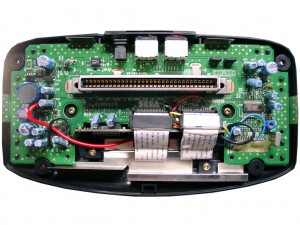
Here you can see the complete eprom attached
Look here for a video showing how the modification is working (german language)
http://www.youtube.com/watch?v=PYxM5u4DBis
english
http://www.youtube.com/watch?v=eQVGKSsld1k

Hi,
I want to do one of these mods, but I do not have an eeprom burner. Do you sell the Mega CD bios chips with the code already on?