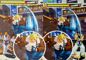
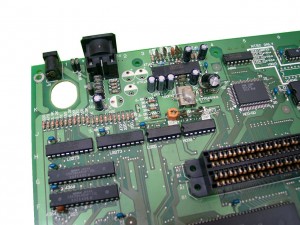
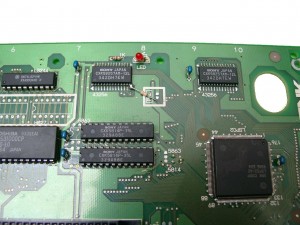
The newer Revision 5 or 6 of Neo Geo have bad RGB-Output Signals. It looks like a grid layed over the picture.
We can take care of the RGB-Fix if you are not able to do it by yourself
To remove the vertical lines you can do the RGB bypass I found here.
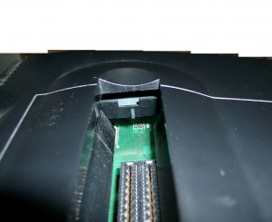
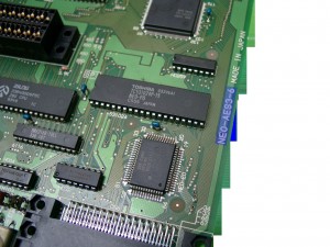
First you have a look into your neogeo to see if you have one of the „bad“ Revisions.
use a flashlight to see the number
Part #1
Removing Capacitors, Resistors and replaceing with 3 75Ohm Resistors
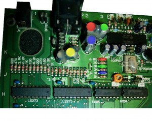
You have to remove the four marked capacitors (red,green,blue,yellow) and the 3 Resistors (red,green,blue).
After this it looks like this
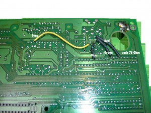
Now you have to reconnect the rgb Signal via 75 Ohm Resistors.
I am using some shrinking tube look here.
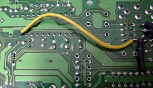
The Sync Signal (yellow) doesn’t need 75 Ohm you can wire it directly
Part#2
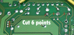
directly at the other side of the mainboard you find the crystal (the cause of the problem)
you have to cut of the rgb-signal in this area, so the crystal can’t sending bad signals into the rgb-wires.
You have to cut both sites to be sure.
cutting done
After further reading the links above, it seems to be allright if you only do Part#2.
When I will do the next neogeo I will check it and give this site an update, because I done first Part #1 and the picture was quite better. After doing Part#2 I didn’t saw any better picture.
Part #3 50/60 Hz
If you have a Pal Revision all games running at 50Hz you have to cut of the connector between the pal jumper.
The following picture is showing a NTSC Console.
Pin 64 of the nearby chip LSPC2-A2 9305 E27 sets 50 or 60Hz.
GND at Pin 64 -> 60Hz
5V at Pin 64 -> 50Hz
