Archive for the ‘NeoGeo’ Category

8BitDo Wireless NeoGeo Arcade Stick

Donnerstag, Mai 23rd, 2019

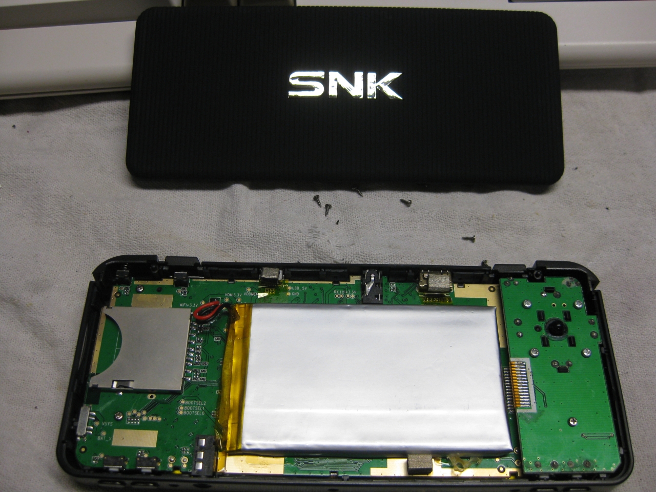
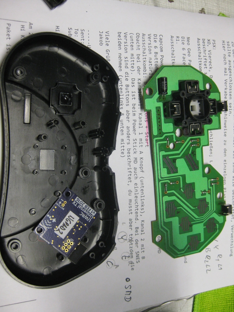
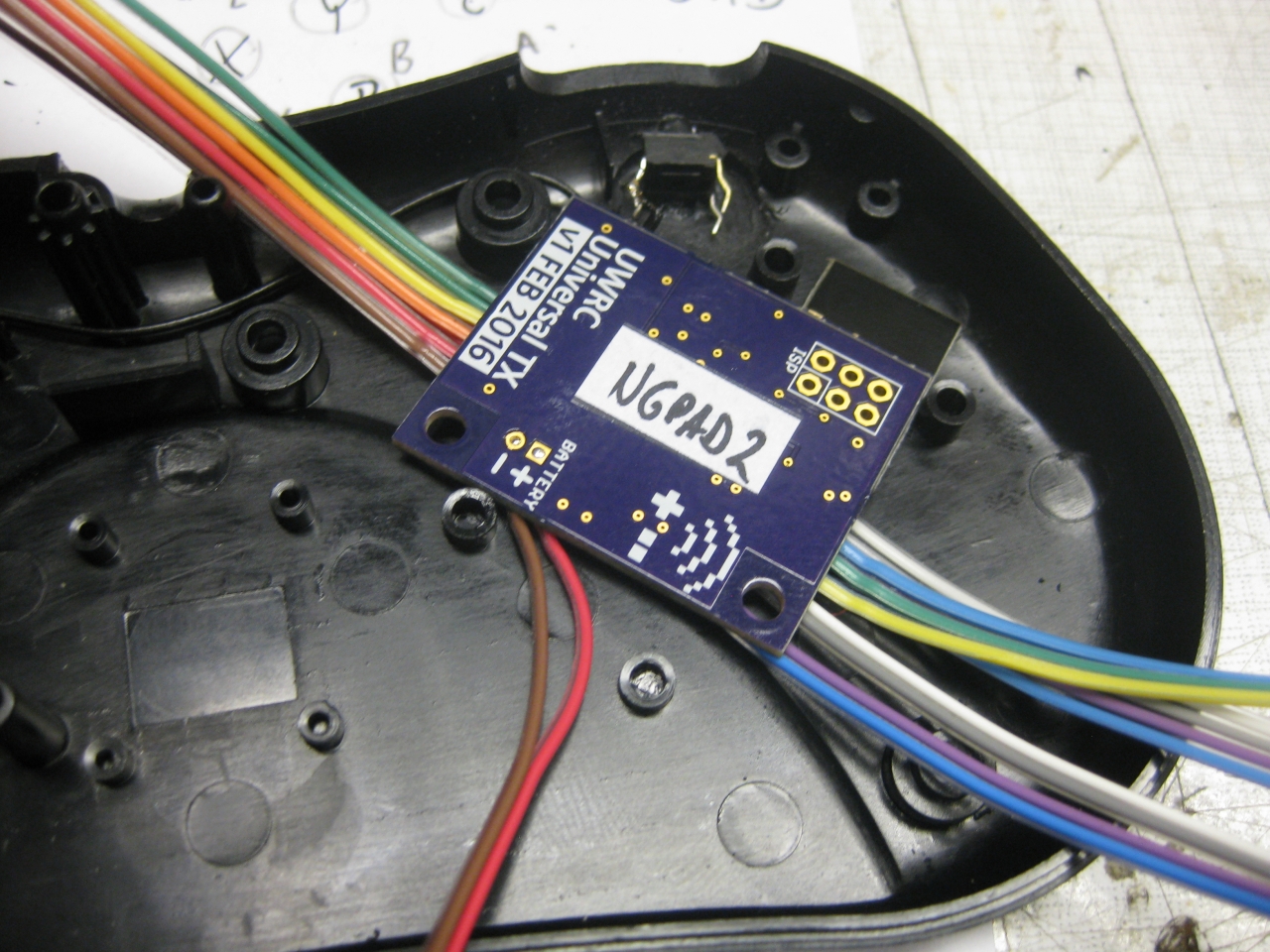
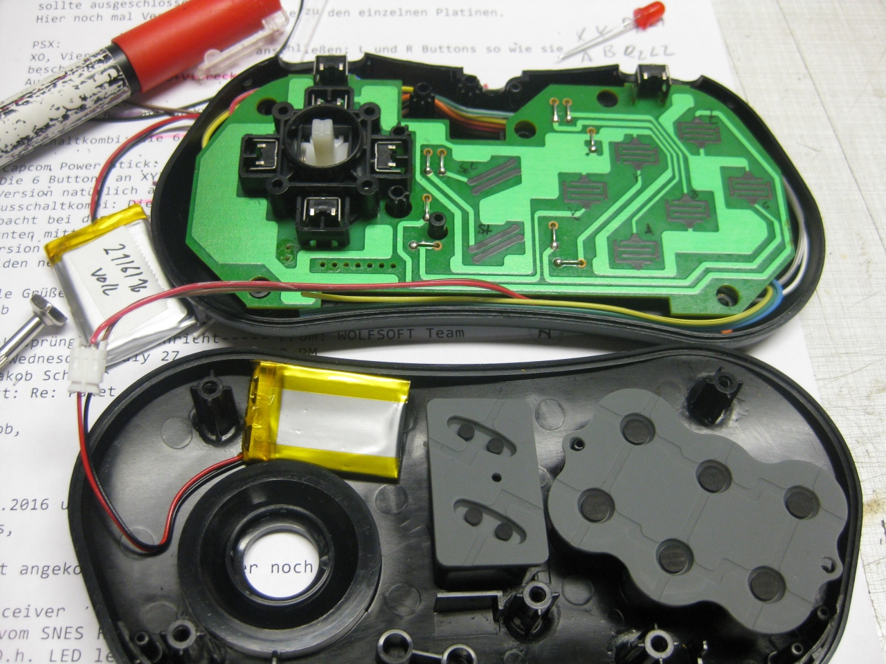
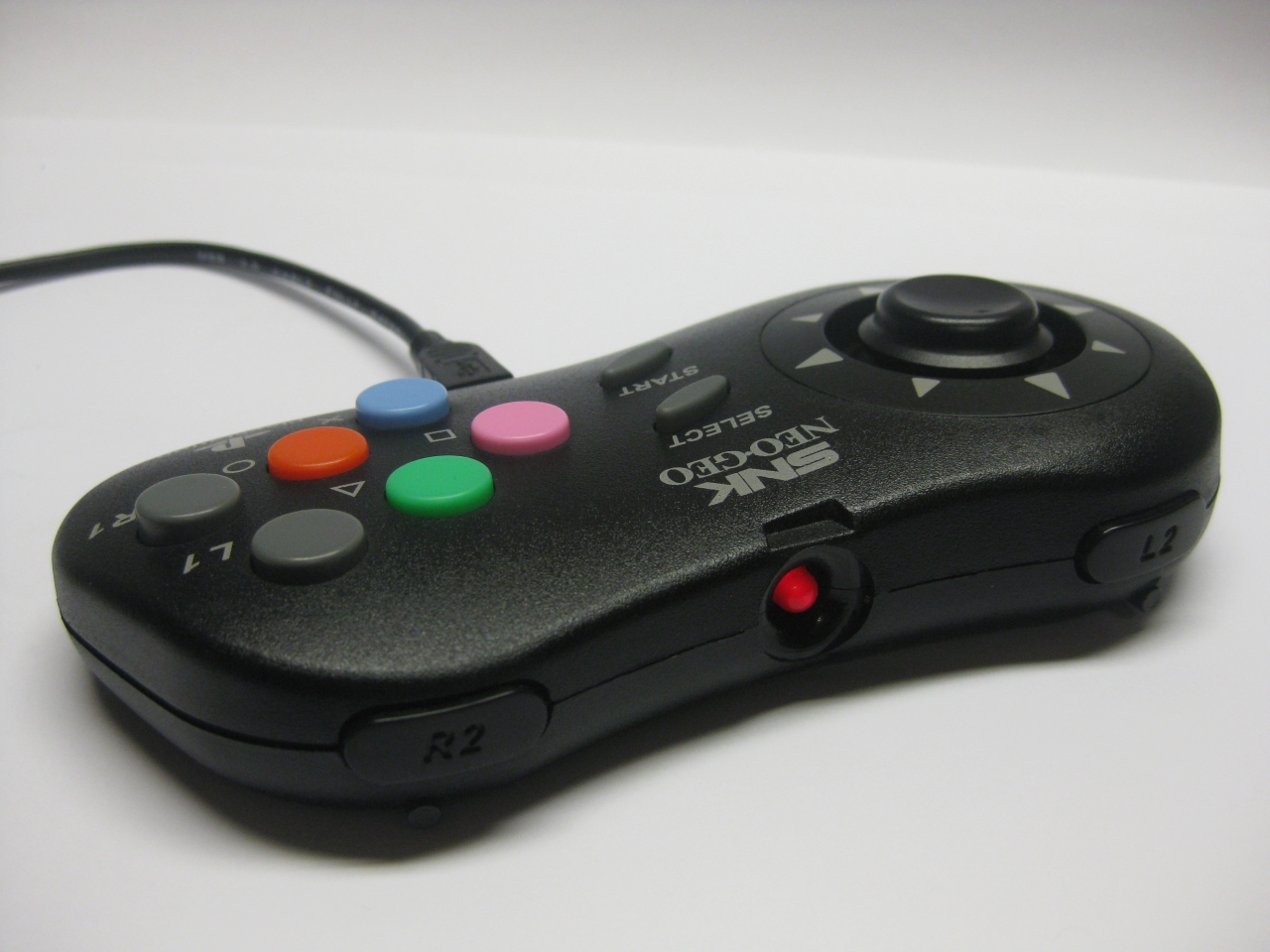
I used a SNES DIY Kit and put it into a original NeoGeo Arcade Stick.
And with my old led mod  it is a cool wireless device. Working on PC, SNES, Switch, XBOX One,PS3,PS4 with the 8Bitdo Adapters….
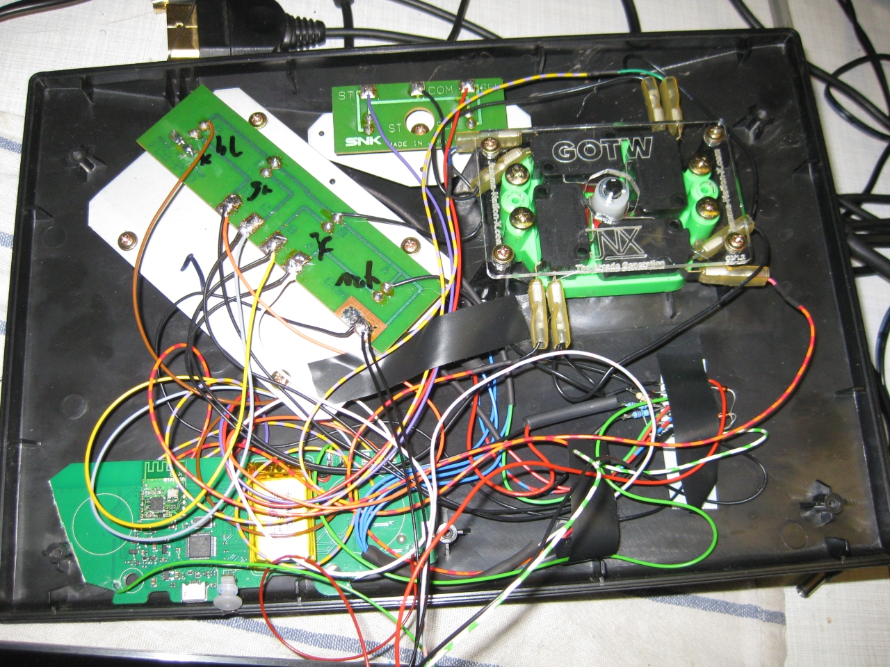
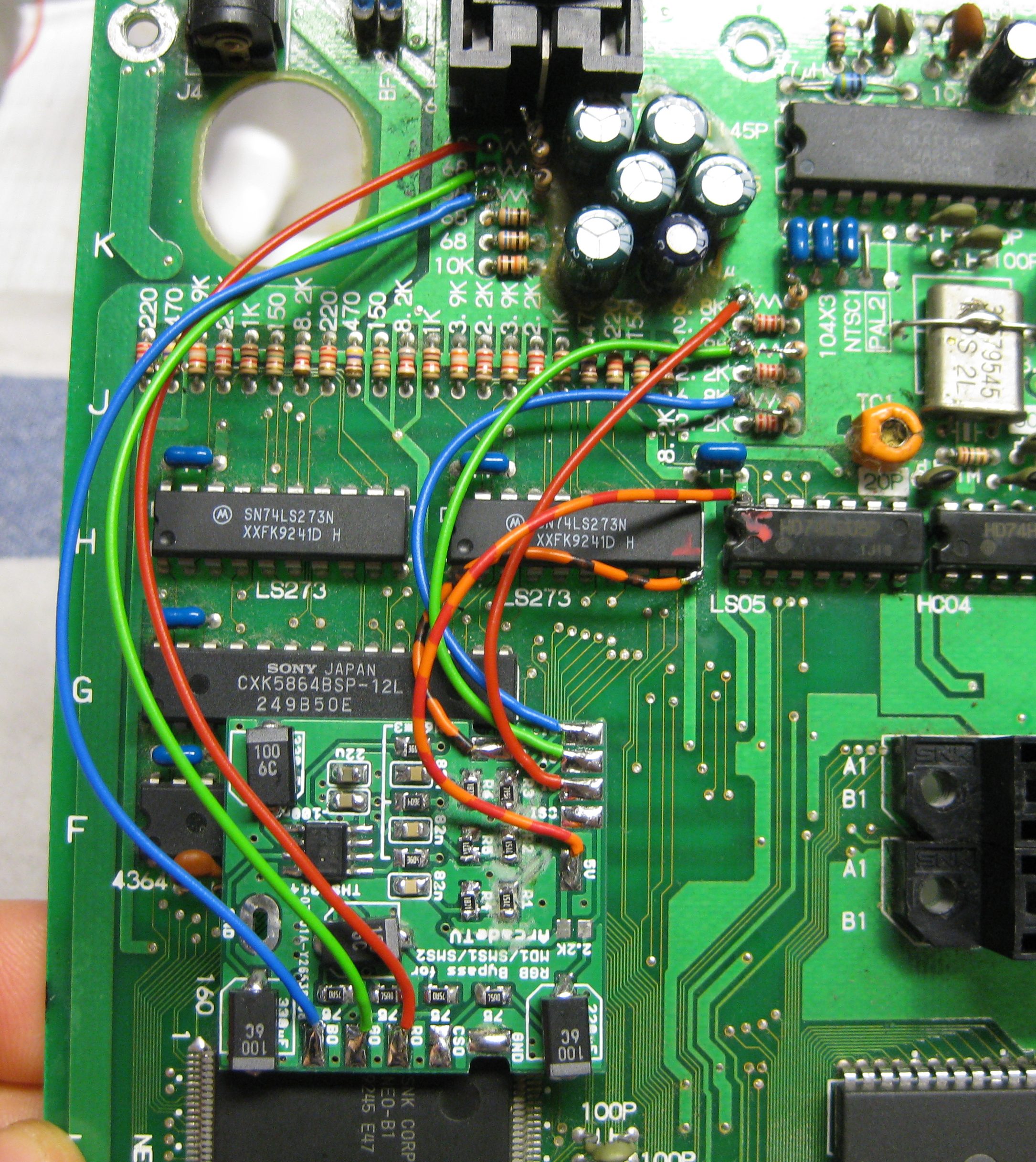
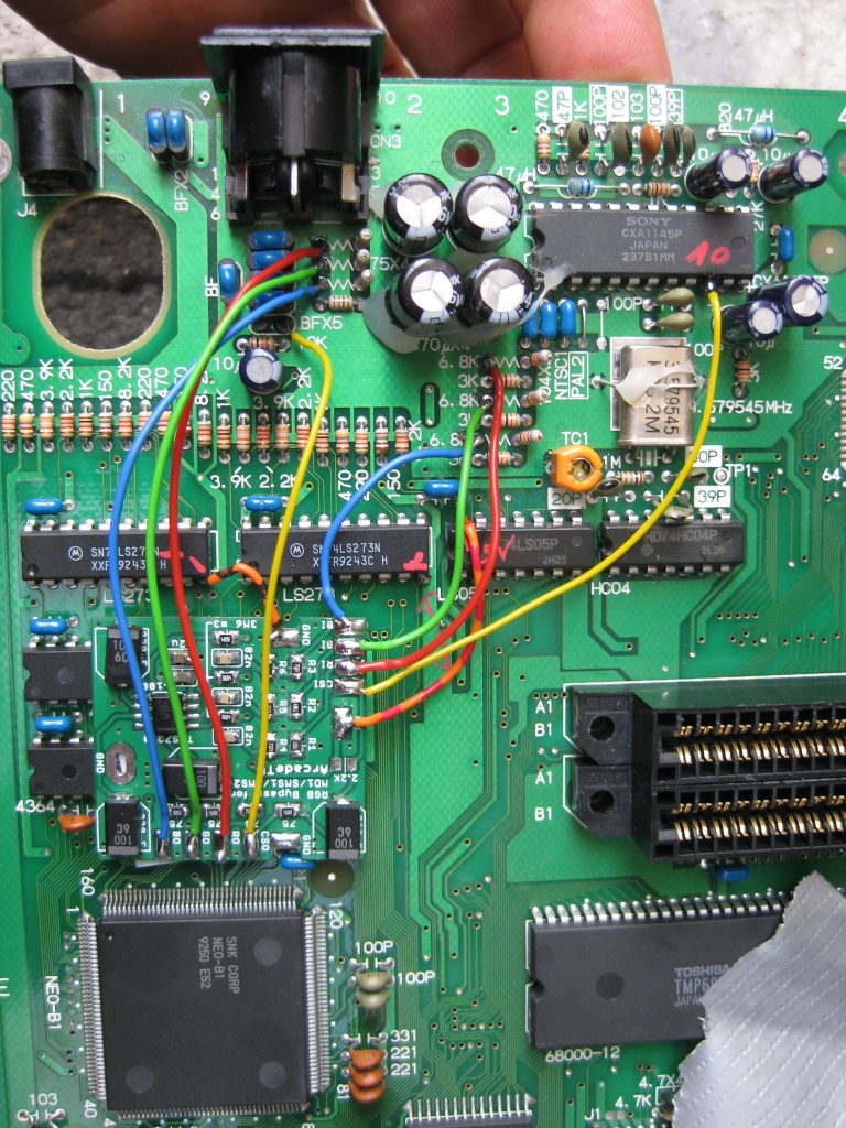
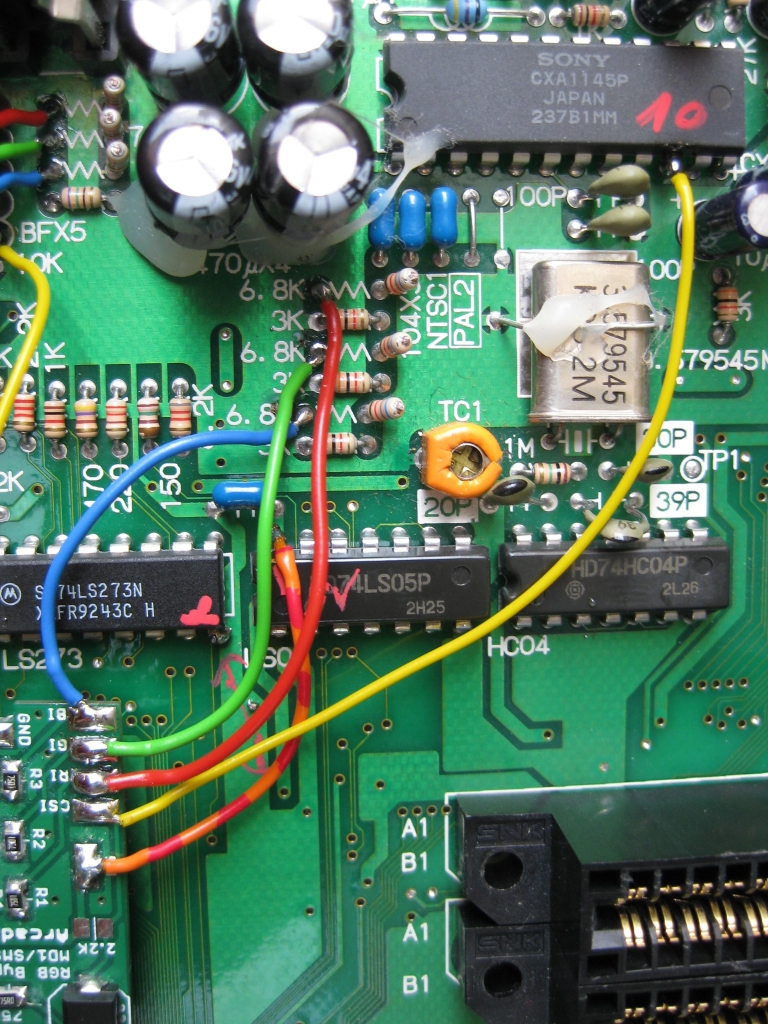
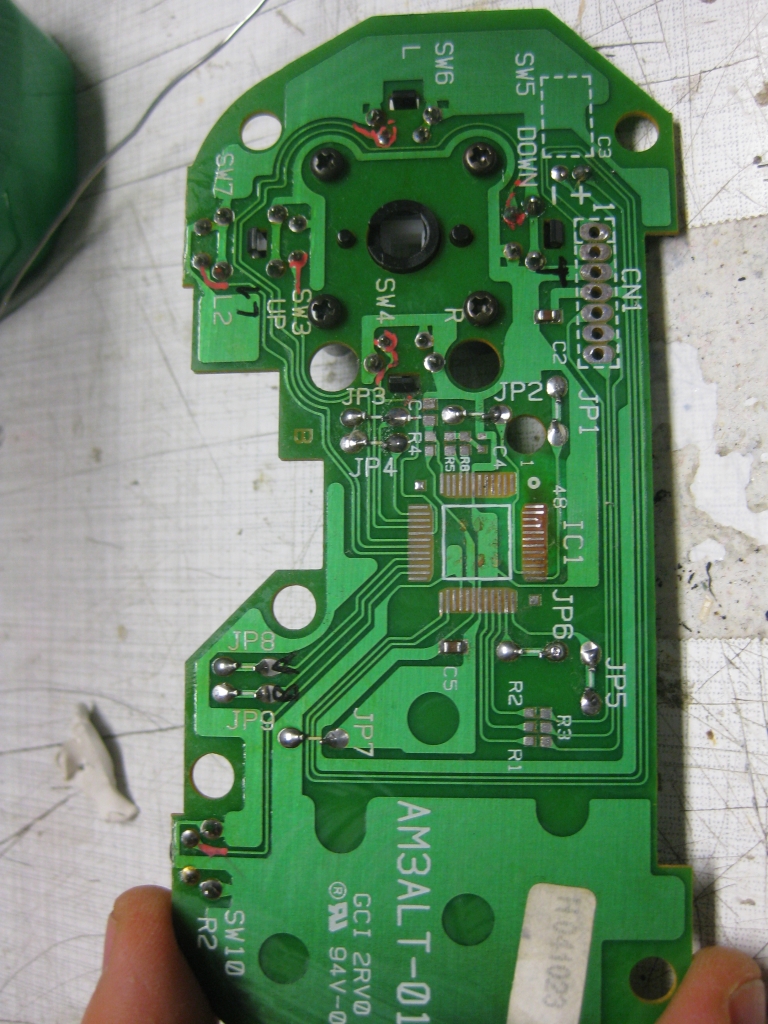
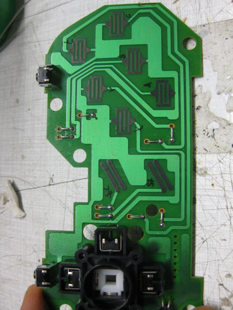
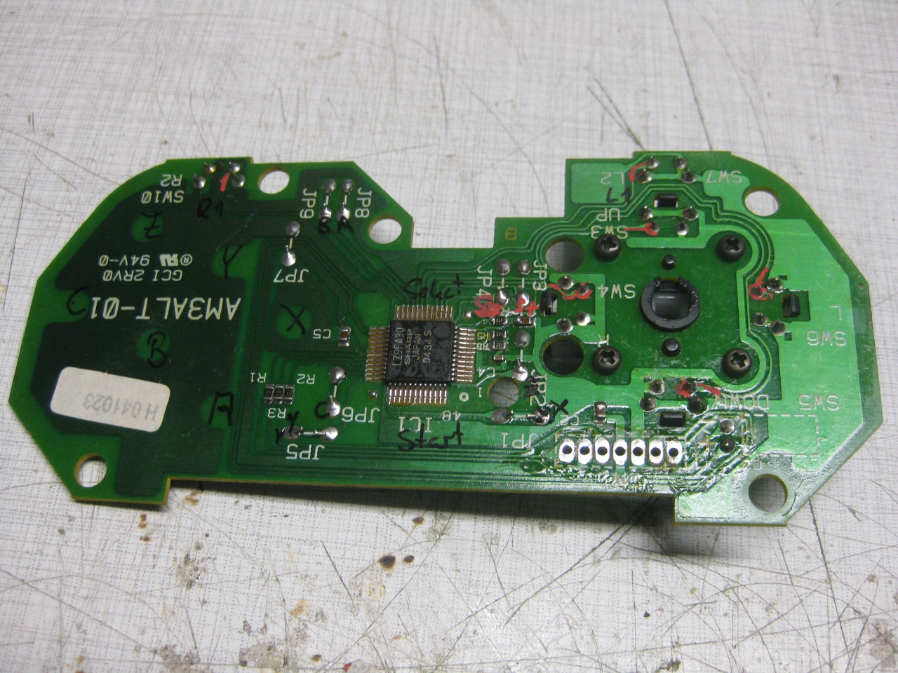
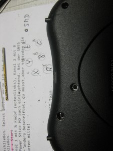
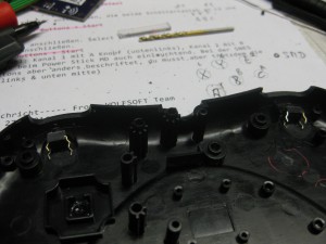
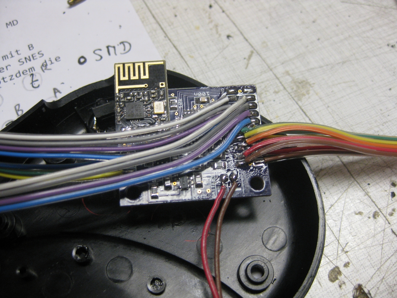
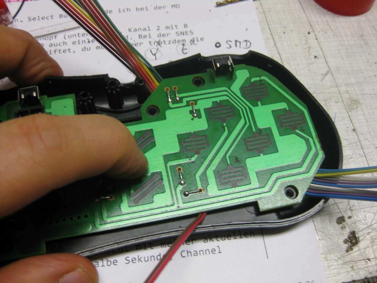
8bitdoneogeo (1)

a lot of wires…

8bitdoneogeo (4)

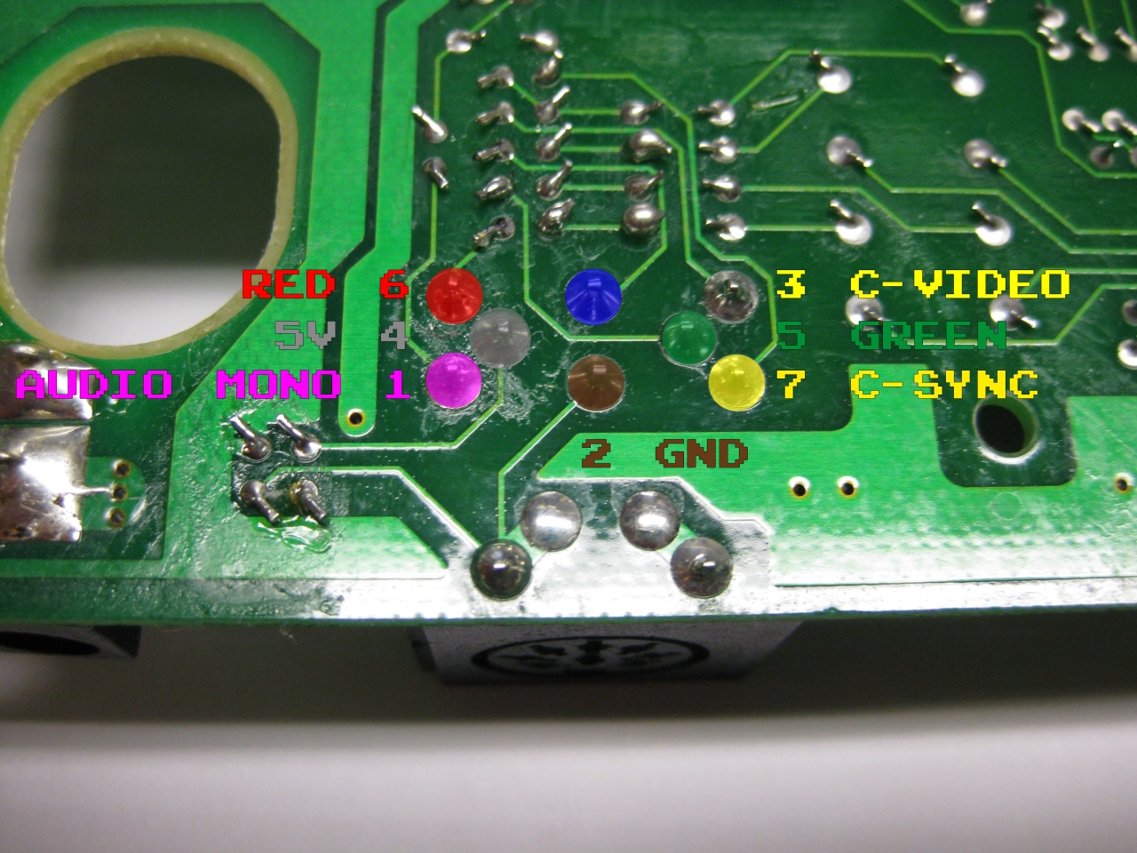
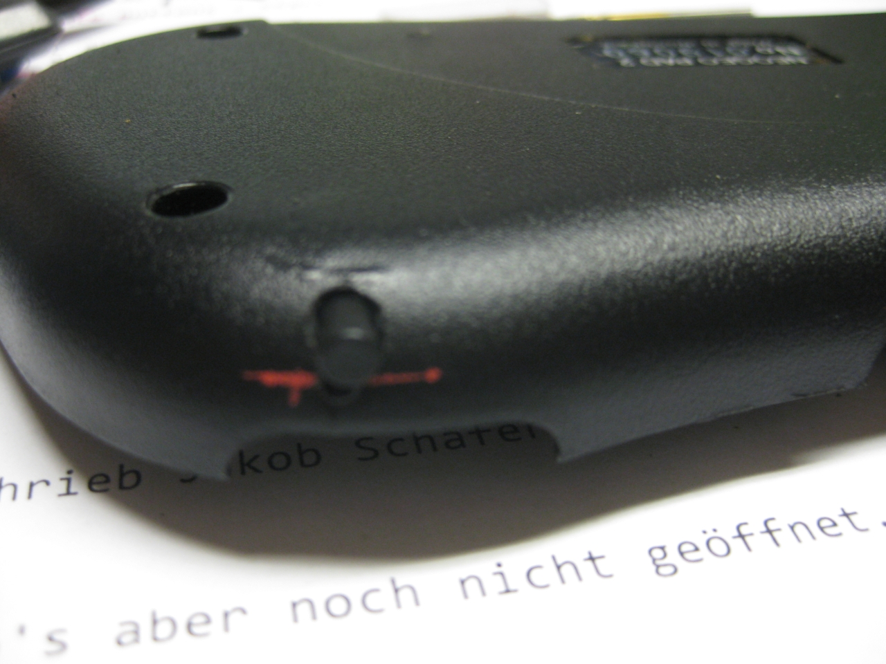
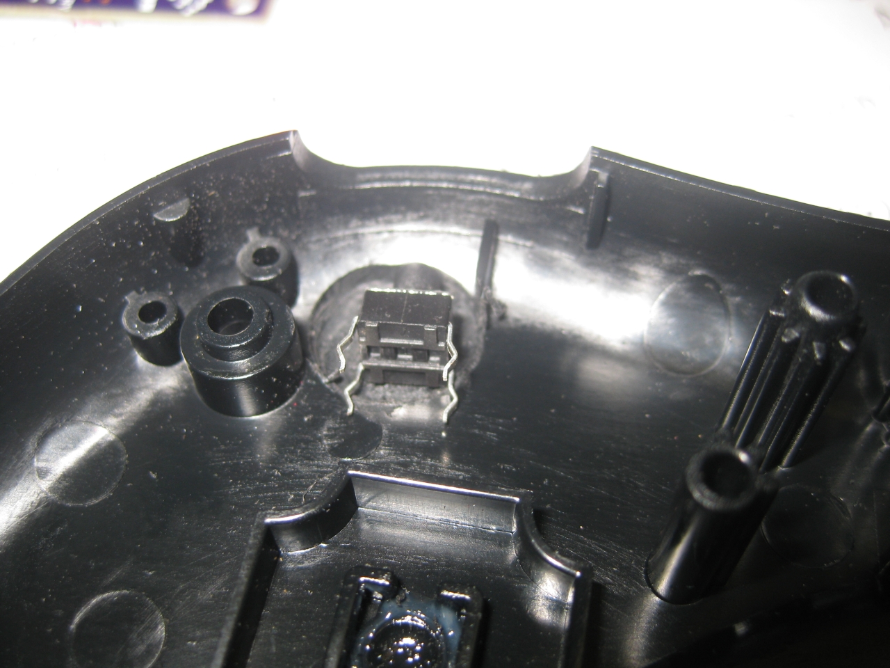
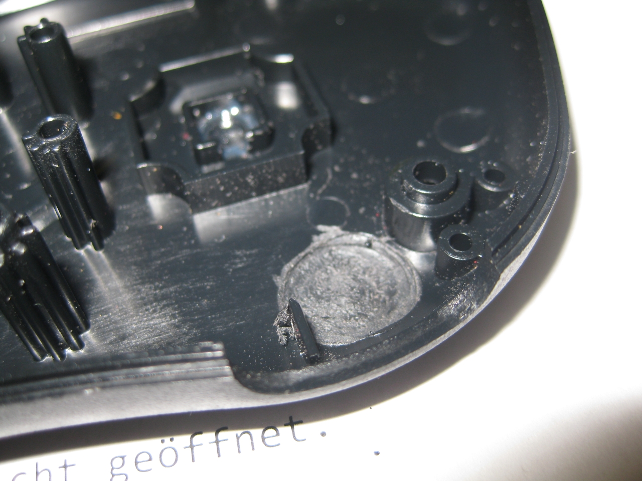
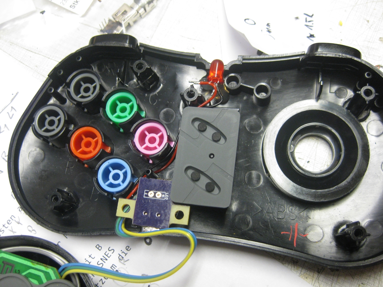
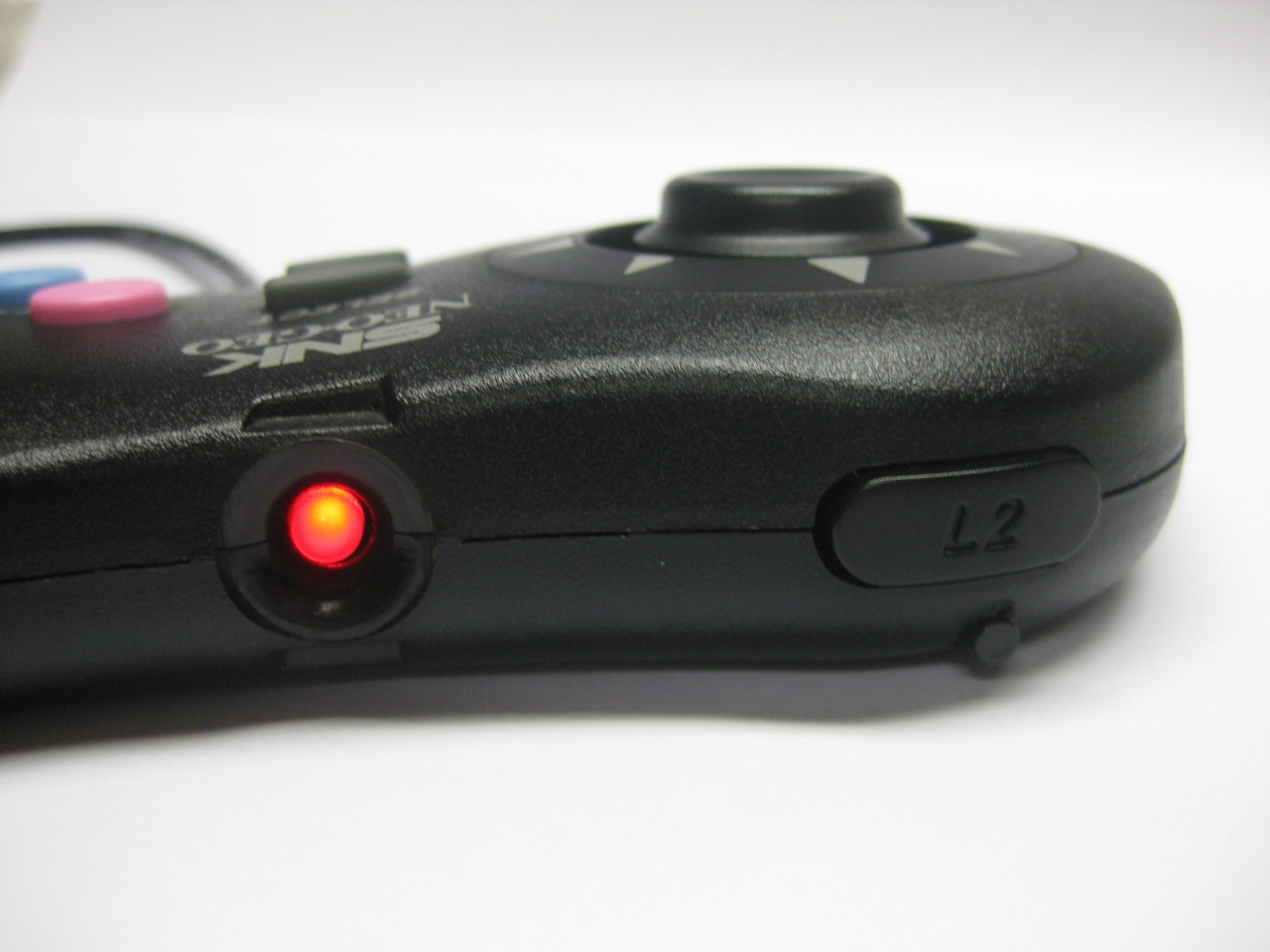
loading connector with led

8bitdoneogeo (7)

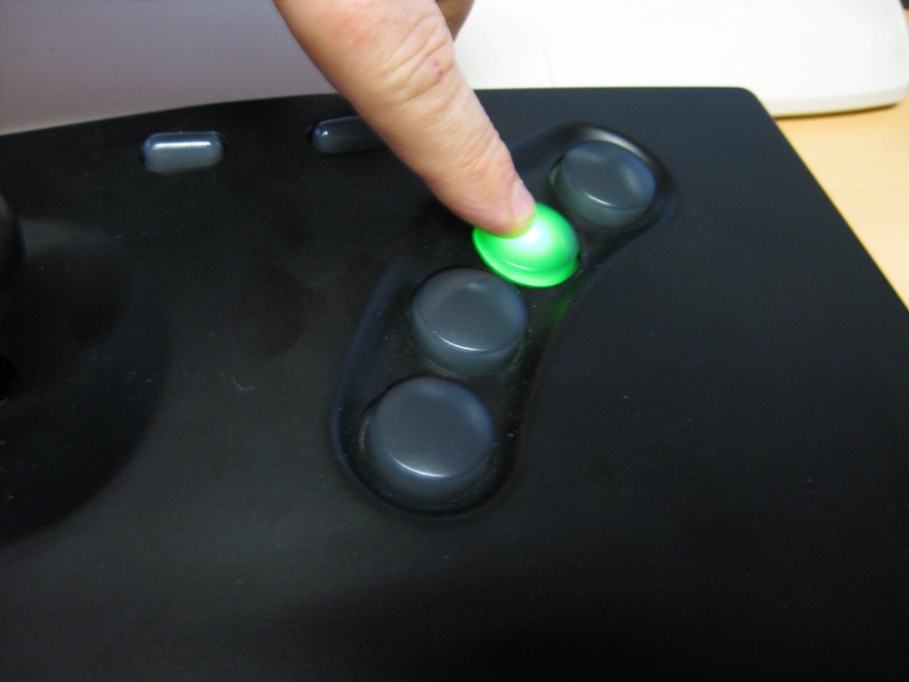
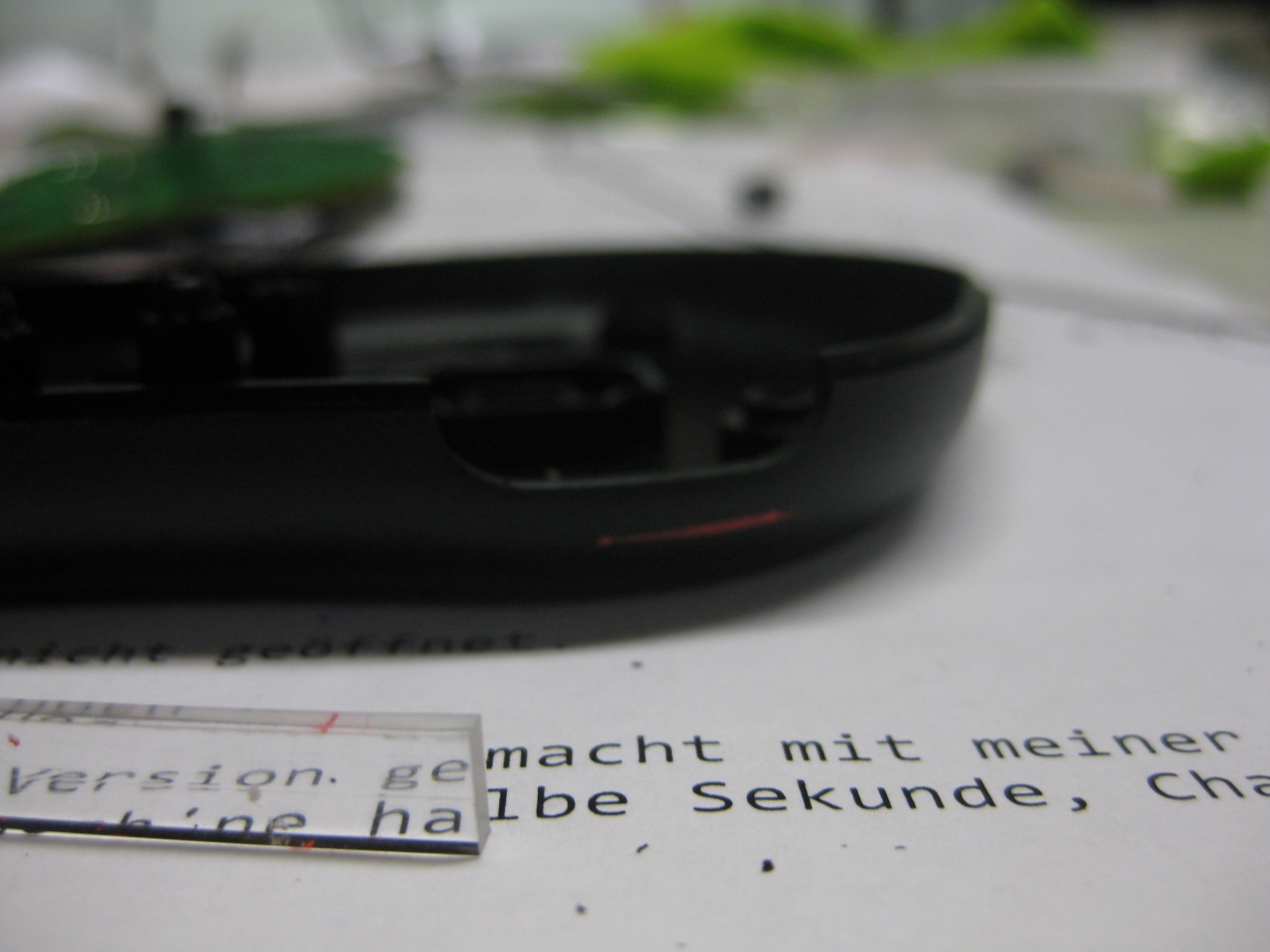
light up when pressing

8bitdoneogeo (6)

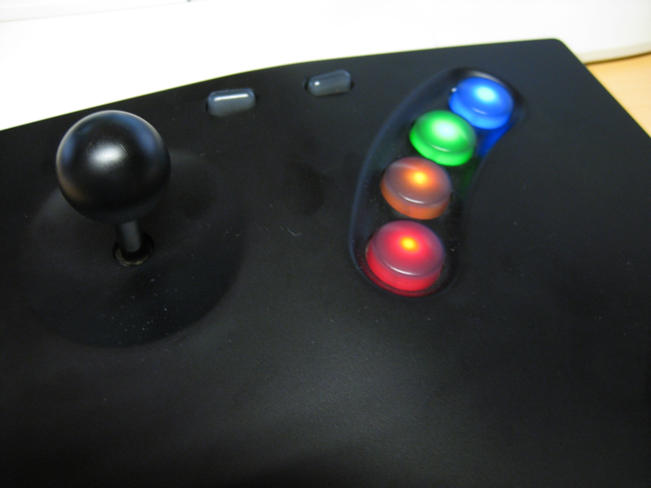
or all four leds permanent on
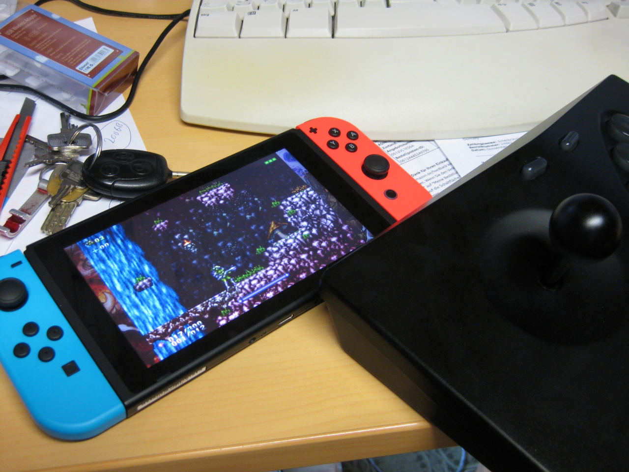
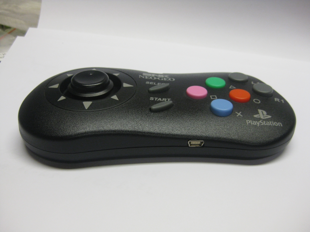
8bitdoneogeo (12)

gunlord wireless with neogeo stick :-)


Neo Geo AES 3-4 RGB Bypass

Donnerstag, September 14th, 2017

here you find the pics for rgb bypass for a neogeo AES 3-4 PCB with THS 3714 amplifier.

No more bad pictures and no more jailbars with perfect picture level thanks to arcade-tv :-)

R1-R3 = 7.1k

R4-R6= 1.9k

IMG_4399

NeoGeo X battery failure

Donnerstag, September 14th, 2017

I was lucky to get a new NeoGeo X Console but the battery was brocken :-(

neogeox_battery_5

So i ordered a replacement and changed it …

neogeox_battery_1

Look at the blown up original battery (never used, brocken, crazy)

neogeox_battery_2

done

neogeox_battery_3

and its working …

NeoGeo AES 3-5 RGB Bypass with THS 3714

Donnerstag, September 1st, 2016

thanks to arcadeTV we have a optimized Version with THS 3714 for NeoGeo AES :-)

-cut left side of the three 6,8k resistors for input rgb input of ths amplifier

-cut the left side of the three 75 ohm resistors for output to the din 8.1

-cut BF for sync output to the din 8.1

the perfect voltage divider values for bypass PCB :

R1,R2,R3=7,51k

R4,R5,R6=2,29k

@ AES 3-5 Mainboard Pin 3 Comp Video and Pin 7 C-Sync are the same on both you will get Comp. Video.

After the modification its is neogeo conform Pin3 comp. Video and Pin 7 C-Sync comming from the THS RGB Bypass PCB

aes3-5_1

aes3-5_zoom

For some help of solder side

neogeo-din-print-solder

cable wiring

scart_NeoGeo-AES_Din-8.1_Layout_2016

UWRC meets NEOGEO PAD2

Montag, August 1st, 2016

thanks to micro I got a TX for a great controller the neogeo CD Controller in the PS2 Version called NEOGEO PAD 2 Controller.


IMG_8993

removing the original controller ;-)

IMG_8986

IMG_8985 IMG_8983

some dremel work

IMG_9006 IMG_9005 IMG_9004 IMG_9003 IMG_9001 IMG_8997 IMG_8996 IMG_8995 IMG_8994

wiring of uwrc

IMG_9008 IMG_9011 IMG_9012

I used a 200mAh Lipo and changed the loading current to 50mA via changing loading R from 10k to 20k

IMG_9019

loading led, usb port, lipo

IMG_9025 IMG_9021

done :-)

IMG_9030 IMG_9029 IMG_9027

NeoGeo MVS adhesive mod

Freitag, Juli 9th, 2010

Hi Folks,

here you can see the adhesive mod of a MVS two Slot System in „NeoGeo Style“:

PS: Great background ;-)

mvs_2er_neogeo_look 001

mvs_2er_neogeo_look 002

mvs_2er_neogeo_look 004

mvs_2er_neogeo_look 005

mvs_2er_neogeo_look 006

mvs_2er_neogeo_look 007

mvs_2er_neogeo_look 008

mvs_2er_neogeo_look 009

mvs_2er_neogeo_look 010

Making of Snow-White and the seven Shockers…

Montag, Juni 14th, 2010

I found some NeoGeo Cases here and cleaned them up with the help of my dishwasher.

They have a lot of scratches and as I am not a friend of black – I prefer WHITE – like the great PC-Engine one of my favorite Consoles. I make use of white spray on a good old NeoGeo AES.

After some spraying it looks like this:

snow_white_smaller_partssnow_white_bottomsnow_white_topsnow_white_01snow_white_02snow_white_03

more pictures:

snow_0

snow_1

snow_2

snow_3

NeoGeo Oldstyle Button LED mod

Freitag, Juni 4th, 2010

After surfing the www for neogeo… I found a modified NeoGeo Joyboard with LEDs.

A great Idea, and some dremel work later…

Nothing new for me. The Buttons in the oldstyle Boards are the same as the NeoGeo Reset Button.
I done this mod weeks ago.  Some RGB-LEDs and Resistors and done…

If you can’t do it, we offer this service:
http://www.wolfsoft.de/shop/product_info.php/products_id/14793

neogeo_duo_3

14739

Video:

I done some upgrade and make the lights switchable.

I am using a analog switch MC14551B to make three modes possible

a) lights off

b) Light on button press

c) all lights on

neo_button_mod_1

neo_button_mod

neo_wiring

NeoGeo AES switchless MOD

Dienstag, April 20th, 2010

I am using a NEOGEO AES3-5 unit for the switchless mod today

neogeo

Rom Part: piggyback

I added a second Bios from Razoola the UNIBIOS. You can get it at www.wolfsoft.de or unibios.free.fr

Here you can find a good tutorial for piggyback the UNIBIOS http://www.mmmonkey.co.uk/

First you have cut pin 2 of the onboard Bio and lift the pin up:

neogeo_duo_1

use a DIP 40 socket to make a future replacement easier

Lift up pin 2 of the mainboard and pin 2 of the DIP-socket

neogeo_duo_2

The PIC 16F630 Part

As usually I am using the switchless mod from seb http://seb.riot.org/saturnmod/

And the inspiration from Pete Grimes Site: http://www.mmmonkey.co.uk/

This time I can’t use sebs pic code „out of the box“.
I have done some lite modifications to the code.
50/60Hz switching is inverted at the NeoGeo and NeoGeo can’t switch between 50/60 Hz during operation. So it is needed to do a reset after switching 50/60Hz.

The Country Mode must reduced from 3 to 2 and I have done some slight changes for make a RGB-LED working. The difference at the RGB-LED it is wired common Anode

You will find the source code here.

PIC 16F630 Wiring

red wire PIC Pin 1 (5V) taken from IC HC04 Pin 14

black wire PIC Pin 14 (GND) taken from IC HC04 Pin 7

red wire PIC Pin 5 to RGB-LED (Resistor 150Ohm)

blue wire PIC Pin 6 to RGB-LED (Resistor 150Ohm)

yellow wire PIC Pin 8 to lifted Pin 2 of the DIP-socket

blue wire PIC Pin 10 to lifted Pin 2 of the onboard Bios

white wire PIC Pin 11 to solder site of mainboard (Reset Signal)

pink wire PIC Pin 12 to PAL Jumper right site (LSPC2-A2 TSOP Pin 64)

grey wire PIC Pin 13 to solder site of mainboard (Reset Button)

remove the pal jumper, solder pink to the right site of the jumper

(left site of PAL1 5V, right site to LSPC2-A2 TSOP Pin 64 for 50/60Hz definition)

neogeo_duo_4

Here you can see the lifted pins

neogeo_duo_5

on the solder site you have to cut one circuit (see red marked area) and solder grey and white

(to split the original Reset Button Signal and make use of the Reset Button via the PIC)

neogeo5

complete mainboard top site
The black wire at the RGB-Led under the Reset Buttons is carrying 5V and taken from a nearby IC

neogeo_duo_6

Now you have to add the RGB Led to the power switch, with help of a dremel.

I done it the same way as pete from www.mmmonkey.co.uk

For more power I am using now a RGB-Led with black wire common Anode 5V

neogeo_duo_3

rgb-led

english video

german Video

NeoGeo AES RGB-Fix

Dienstag, Dezember 1st, 2009

The newer Revision 5 or 6 of Neo Geo have bad RGB-Output Signals. It looks like a grid layed over the picture.
We can take care of the RGB-Fix if you are not able to do it by yourself

left site: verticallines, right site: OK!

left site: verticallines, right site: OK!

To remove the vertical lines you can do the RGB bypass I found here.

JammaNation X

mmmonkey

NeoGeo Forum

First you have a look into your neogeo to see if you have one of the „bad“ Revisions.

use a flashlight to see the revision of your neogeo board

use a flashlight to see the revision of your neogeo board

use a flashlight to see the number

This can help too

Here you can see the Layout Revision

Here you can see the Layout Revision

Part #1

Removing Capacitors, Resistors and replaceing with 3 75Ohm Resistors

Remove the 4 capacitors and 3 resistors

Remove the 4 capacitors and 3 resistors

You have to remove the four marked capacitors (red,green,blue,yellow) and the 3 Resistors (red,green,blue).

After this it looks like this

removed capacitors and resistors

removed capacitors and resistors

Now you have to reconnect the rgb Signal via 75 Ohm Resistors.
I am using some shrinking tube look here.
The Sync Signal (yellow) doesn’t need 75 Ohm you can wire it directly

3 resistors and sync wire

3 resistors and sync wire

Part#2

directly at the other side of the mainboard you find the crystal (the cause of the problem)

you have to cut of the rgb-signal in this area, so the crystal can’t sending bad signals into the rgb-wires.

cuting rgb signal

cuting rgb signal

You have to cut both sites to be sure.

cutting done

cutting done

cutting done

After further reading the links above, it seems to be allright if you only do Part#2.
When I will do the next neogeo I will check it and give this site an update, because I done first Part #1 and the picture was quite better. After doing Part#2 I didn’t saw any better picture.

Part #3  50/60 Hz

If you have a Pal Revision all games running at 50Hz you have to cut of the connector between the pal jumper.

The following picture is showing a NTSC Console.

Here you can see a NTSC Console in 60Hz Mode

Here you can see a NTSC Console in 60Hz Mode the 0 Ohm Resitor gives GND to Pin64

Pin 64 of the nearby chip LSPC2-A2 9305 E27 sets 50 or 60Hz.

GND at Pin 64 -> 60Hz
5V at Pin 64 -> 50Hz