Archive for November, 2009

easy mod of a neogeo Stick 2

Montag, November 30th, 2009

Hi Folks,

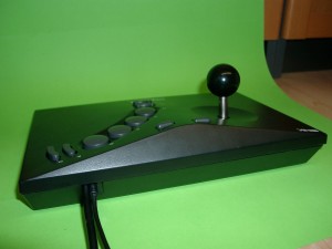
we have some NeoGeo Sticks 2 for PS3 in stock.
But it works not @ the good old neogeo. So I make an easy hack for the neo geo.
After the mod it works on PC, PS3, Neo Geo, NeoGeo CD, MAK and Clones. (Attention do not connect both PS3 and NeoGeo at the same time).
You can buy it ready for use if you want or make it yourself.

I make use of 6 Buttons at the neogeo connector.

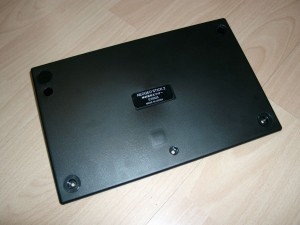
opening

opening

you have to remove 3 of the 4 rubbers.

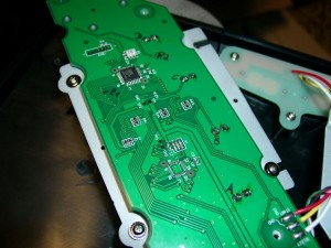
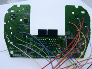
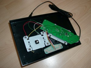
first look at mainboard

first look at mainboard

checking buttons a,b,c,d,e,f

checking buttons a,b,c,d,e,f

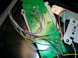
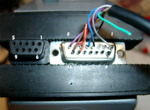
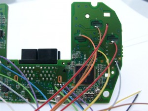
wiring with neogeo cable

wiring with neogeo cable

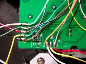
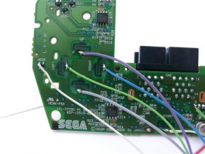
zomed view, the pins for direction and select,start are marked on the mainboard

zoomed view, the pins for direction and select,start are marked on the mainboard

cutting pvc to get both cable out of the neogeostick

cutting pvc to get both cable out of the neogeostick

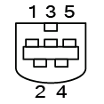
Here you can see the NeoGeo Connector:

1 GND brown
2 Feuer E (5) red
3 Select (Coin) orange
4 Feuer D (4) pink
5 Feuer B (2) yellow
6 Rechts darkgreen
7 Unten lightgreen
8 5 V darkblue
9 N.C. lightblue
10 Feuer F (6) purple
11 Start grey
12 Feuer C (3) white
13 Feuer A (1) black
14 Links brown/white
15 Oben black/white

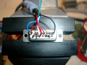
If you didn’t want to see 2 cables out of the neogeostick you can make use of a Sub-D 15 connector and a separate cable.
upcb Amiga Cable

Dienstag, November 24th, 2009

Hi Folks,

today it’s time to make amiga upcb working.

In the original Document of neogeo.h the +5V at older Videogame Systems are defined at Pin 5 of the SUB-D 9 pin Connector, but for amiga it’s wrong: Here we can find it at Pin 7 of SUB-D 9 pin Connector.

Amiga Pinout

Amiga Pinout

Amiga

Pin Description

1 UP (brown)
2 Down (red)
3 Left (orange)
4 Right (yellow)
5 (green)
6 Button 1 (blue)
7 +5V (purple)
8 GND (grey)
9 Button 2 (black)

Sub D 15

Pin Description

1 8 (GND) grey

2

3

4 9 Button 2 (black)

5 6 Button 1 (blue)

6 4 Right (yellow)

7 2 Down (red)

8 5 (VCC 5V) (purple)

9 Low

10

11

12

13

14 3 (Left) orange
15 1 (Up) brown

Buttons1

Buttons1

Buttons

Buttons

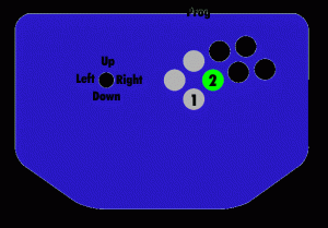
If no Buttons are working. Try to press the 3 grey Buttons at powerup or
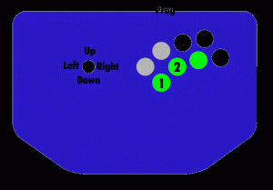
Press the three green Buttons at powerup

Pinbody Part #3

Montag, November 16th, 2009

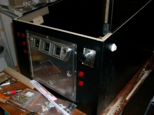
The frontsite needs most time because of the holes, frontdoor.

The buttons done with two different hole sizes, because of the authentik look deeper in the wood.

holes, holes, holes

holes, holes, holes

mounted front

mounted front

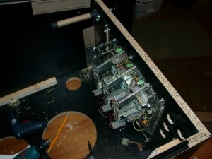
insite view

insite view

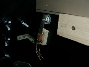
leaf switch

leaf switch

original PB Leafs for the wright feeling

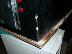
leg holes

leg holes

first complete mounting

first complete mounting

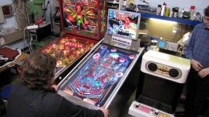
On Saturday 14. of November, I drived to the DADDELParty @ Luigi and Capt. Kirk (Neustadt a. Weinstr.)
The first viewing and playing was great.  Please posts comments

First public test

First public test

DC Padhack

Montag, November 16th, 2009

Hi Folks,

here you can find how to a padhack for the original DC Pad including making of the DC-Cable for it.

Buy upcb

Ordering Dreamcast Pad for Padhack

Ideal XBOX360 Pad for Padhack

Padhack:

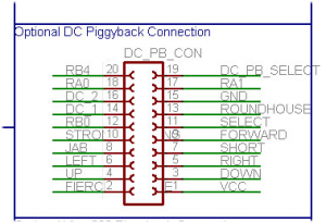
Piggy Connector Pinout

Piggy Connector Pinout

Pin Color
1 black VCC Pin 2 (blue) Pin 2 CN1
2 white 7 Hard Punch FIE=FIERCE Left Trigger
3 grey DOWN DOWN
4 purple UP UP
5 blue RIGHT RIGHT
6 green LEFT LEFT
7 yellow 1 SHO=SHORT Light Kick A (green)
8 orange 5 JAB Light Punch X (blue)
9 red 2 FOR=FORWARD Medium Kick B (red)
10 braun 6 STR=STRONG Medium Punch Y (yellow)
11 black L-PB SEL=SELECT
12 white R-PB RB0 Start Start
13 grey 3 ROU=ROUNDHOUSE Strong Kick Right Trigger
14 purple
DC 1 Pin 1 (red)
Pin1 CN1
15 blue
GND  Pin 3 (black)
Pin3 CN1
16 green
DC 2 Pin 5 (white)
Green usb cable
17 yellow RA1 LTrigger
18 orange RA0 LButton
19 red DC PB Select
20 braun RB4 Guide

Pictures:

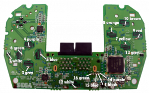
Wiring Points

Wiring Points

Wiring in Detail1

Wiring in Detail1

Wiring in Detail2

Wiring in Detail2

Wiring in Detail3

Wiring in Detail3

Dreamcast Cable:

Pictures of Sub-D 15 pin male:


soldering

soldering

DC Pinout

DC Pinout

DC-Connector CN1 Sub-D 15 pin male: Pin Description Pin Description 1 Serial A (red) 1 3 (GND) 2 VCC +5V (blue) 2 Low 3 GND (black) 3 Low 4 Sense (green) 4 High 5 Serial B (white) 5 High 6 Low 7 Low 8 2 (VCC +5V) ______________________ 9 NC - 10 High 11 High 12 NC - 13 1 Serial A (red) 14 5 Serial B (white) 15 Low

the body continues..

Donnerstag, November 12th, 2009

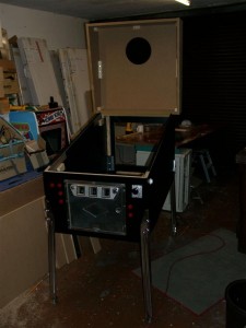
Today I done the backbox and doing some assembling of the body

I hope I am ready on saturday with a „beta“ Version. And can take it to the

Party at Luigi and Capt. Kirk…

backbox

backbox

pinbody assembling

pinbody assembling

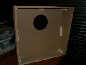
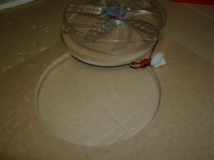
Accurate hole for fan

Mittwoch, November 11th, 2009

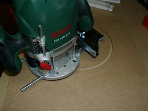
Its my first time to use a router for a accurate hole.  First test looks good.

router@ work

router@ work

hole done

hole done

Pinbody Release 2.0

Dienstag, November 10th, 2009

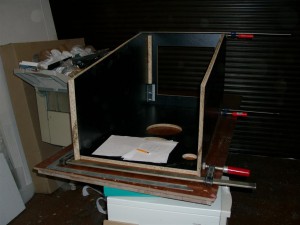
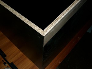
I changed my mind from mdf to a material in black.

It needs more accuracy in wood preparation like diagonal cutting

The advantage of new material is no need to paint :-)

diagonal cutting

diagonal cutting

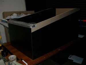
First assembly

first assembly in black

first assembly in black

Pinbody Part2

Freitag, November 6th, 2009

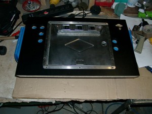
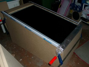
For the first checkup, LCD inside

LCD inside

LCD inside

PinBody Part 1

Mittwoch, November 4th, 2009

I am currently building the body of the pinball.

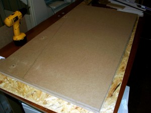
Fist I have to cut down the sides so it looks like an pinball.

I screwed both together and make one cut, so both sides are identical

cutting two sides in one working prozess

cutting two sides in one working prozess

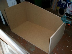
For a first feeling i put the wood parts together

First buildup

First buildup

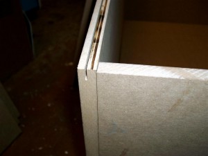
After this I must do an T-Molding for the PVC.

T-Molding for pvc holder glass

T-Molding for pvc holder glass

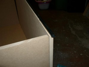
The PVC will hold the glasses of the playfield.

pvc holder for glass

pvc holder for glass

Here is the first look including siderails + lockbar

siderails+lockbar

siderails+lockbar

The next step is to measure the size of the playfield glas for ordering it..

to be continued