Archive for the ‘Virtual Pinball Cabinet’ Category

WPC95 Style Speakerpanel 32Zoll Cab Version

Dienstag, Mai 31st, 2011

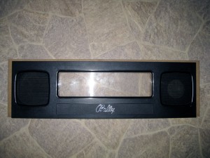
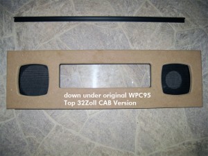
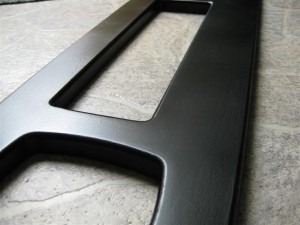
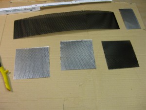
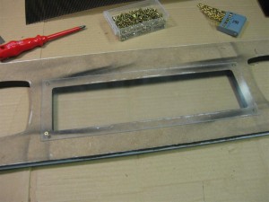
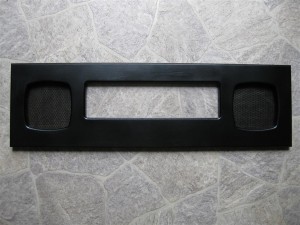
As it is hard to find original wpc95 Speakerpanel and 30Zoll LCD are rare to find. I make a new WPC95 Style Speakerpanel grows a little bit wider and higher so it fits for a 32Zoll Backglass Cabinet.

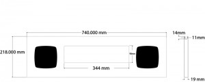
Here you can see some detailed blueprints and pics:

wpc_blueprint

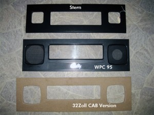
Here you can see a comparsion between different original Speakerpanels

wpc_panels_comparsion

It is a little wider and higher. It can be cutted if needed to original WPC95 size

wpc_comparsion

looks identical

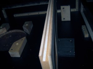
wpc_sandwitch

for the backglass

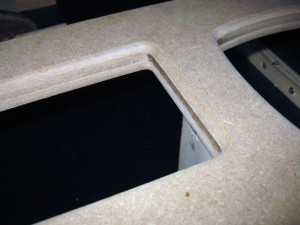
wpc_cut

closeup view

wpc_closeup1

After some spraying it looks like this

speakerpanel_00

Some speakergrill and plexiglas

speakerpanel_01

speakerpanel_02

speakerpanel_03

Speed controlled Shaker via PWM for Visual Pinball

Donnerstag, Januar 20th, 2011

Hi everybody,

we currently using our shaker in the cabs digital only.

But we have a ledwiz as a outputdriver and its capable to do PWM to make eg. Leds „dimming“.

So I tried a Dual-H-Bridge, to make it possible to change the RPM of the shaker.
(Now there is no need of a coupler Relais for this anymore)
It works in digital way as the coupler Relais but if you output PWM to the channel, we can drive the RPM of the shaker and make the effect more or less intense.

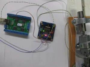
shaker_pwm_all

As we use most output of the ledwiz with 12 V and the signal output is inverted at the screwconnectors I must get the PWM Signal of the Ledwiz directly.

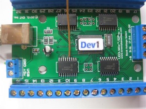
shaker_pwm_pwm_pin_4_solder

I am using Output 12 of the Ledwiz for the shaker. So I have to make a wire to the 2nd ULN Pin 4 (it will be the Signal Input for the PWM Driver.

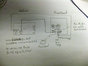
Here is a shematic how to connect all together

shaker_pwm_shematics

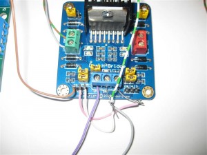
zoom:

shaker_pwm_dual-h-bridge

The Leddrive is using dezimal values from 0 to 48 to make a output from o% to 100% power.

As we have a shaker it needed a minimum of 20 to startup and rotate.

If we want to make low sensitive effects it is needed to startup up the pwm with around 20 for a short time and after this we can reduce it to the final value like eg. 7.

Hope silver can add this feature in the code.

There will be needed two parameters to enable the shaker:

a) a timer how long the shaker rotates

b) the intensive from 0 to 48 for the output of the shaker

c) if the values <20 we need to startup with 20 for a short time and the to right lower value.
I don’t know if its necessary, because do we feel shaking less than 20?

Here you find a video:
Video:

Video showing different power Levels:

Royal Rumble for PinMame

Montag, November 1st, 2010

After month of using my virtual pinball cabinet with „only“ two Solonids for the flipperfinger and getting a real MM Pinball in August, I realised we are in need of more „ForceFeedback“ for our virtualpinball Cabinets.

After talking with chriz99 about this we posted in differnet forums and found Manofwar (the programmer) with Ext2k as betatester. They will release it when it will come out of the betastate…

I presented the new rumble feature last Saturday here in germany at the flippermuseum.eu and it was great.

So here are some infos about the upgrade I done.

I/O Port Device

To get Solonoids to work we choose the ledwiz32 from www.groovygamegear.com.
It can drive 32 Outputs and have the ability to make RGB-Colors with PWM dimmable.
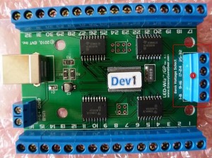
ledwiz

It can drive up to 4 different Voltages for each of 8 Outputs. And the max is 50V per Output @500mA.

As the planed highpower Leds and solonids pulls a lot of current, I done some extra wires for the positive site like this. I don’t know if its needed but I want to be sure nothing goes wrong…
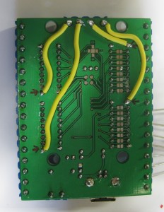
gnd_update

The Goal

To see what we want to upgrade look here (Thanks to chriz99 for the picture):
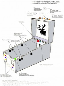
where_to_playe

Royal Rumble with seven Solonids

In my first step I added 5 more Solonoids. So we have a total of 7 Solonoids

  • two in front for the flipperfingers
  • two for the slingshots
  • two in the back for effects like bumpers
  • one in den center for eg. bumpers too

I have four with 24V from Gloeckner Moeller and three Siemens like chriz99/Ext2k.

Here you can see where I place the 7 solonids (marked red)
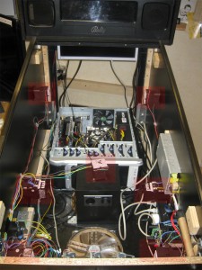
solonoids_position

Separate Power Supply

I used a power supply from a german electronic store with 12V and 5V like this
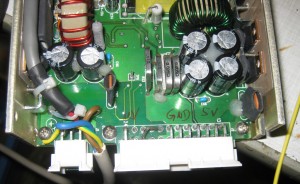
powersupply

Make sure to use separate fuses for the powersupply, so nothing can’t go wrong!
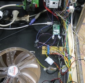
fuses

Colored Flipperbuttons

We planed to use for the main flipperbuttons in transparent with RGB-Leds, so we can make it lite up in every color. It is planed to make them light up in the original color of the selected Pinball Table. So we have the same color of the Button as in the original Pinball Cabinet.

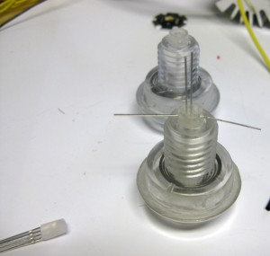
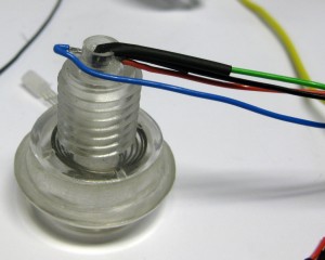
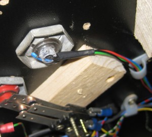
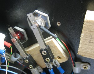
I am using a 5mm RGB-Led for this. The problem was if I put it to the site of the transparent button the color was not bright enough. So I tried to put the Led into the flipperbutton.

The original hole must be 5mm and I done it like this:
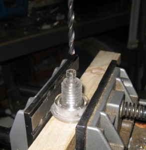
FB_RGB_1

FB_RGB_2

FB_RGB_3

FB_RGB_4

FB_RGB_5

FB_RGB_6

Replay Knocker

I added a replay knocker, but at the current time its not connected, because it takes a lot of current and an higher voltage (50V). So it will be connected later.. with the help of a separate relais that can handle this.
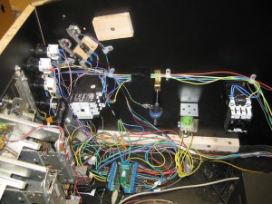
cab_view_1

Shaker

Missing at the moment. But it will rock the system later…

Flasher Effects

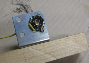
For „Flasher Effects“ I am using High Power RGB-Leds with 3W.

rgbw_led

I done it for a first try this easy way
rgb_highpower

rgb_highpower_1

The Gameplay and feeling

after adding all thes hardware it was time to test it.
For the first try I used the STNG Table and uses the config from Ext2k/Manofwar.
I added the slingshots via the Solonoid Documentation of the original STNG Pinball.
And the Autoplunger to the 2nd right Solonoid. As you know the table shots 4 Balls at startup into the table.

And I added the Bumper to Solonoids.

And added the flasher to the slingshots for a fast test.
So it lights up, when the ball hits a slingshot.

I haven’t so much fun for years with this rumble upgrade!

Thanks to Manofwar! and the betatesters… Virtual Pinball is coming more real as you can imagine.

Frontsite finishing

Freitag, September 17th, 2010

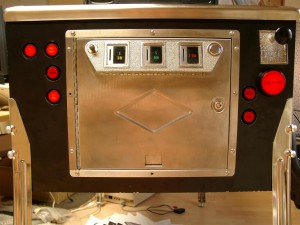
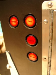
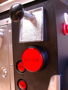
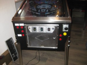
Today I done some Text for the Buttons and here we go and it looks a lot better as before:

pinball_door_01

pinball_door_02

pinball_door_03

Multi Pinball Virtual

Dienstag, August 10th, 2010

Today I have some time to make a little video of the virtual Pinball of us.

More Infos Here

Forcefeedback with Optocopples for PinballCabs

Sonntag, Mai 16th, 2010

As I described before. I am using a „big“ Solonoids (Relais) for forcefeedback of the flipperfingers.

First I used one of the solonoid contact to trigger the Keyboardencoder.

The problem of this big relais is, that its a short delay between flipper button pressing and sending the signal to the encoder.

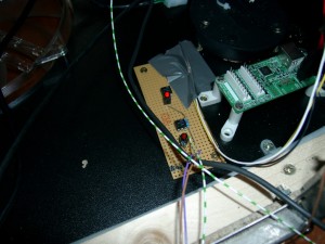
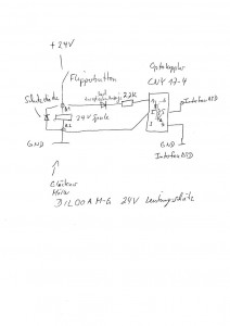
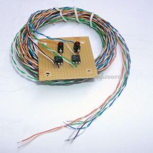
So I used a little optocoppler to sent the signal faster to the keyencoder.

The signal is wired parallel and there is no more delay

optocoppler

cny17-4

Here you can see the kit we offering. It includes long wires to place the solonoids nearby the flipperbuttons and you can reach the keyencoder too.

14798

You can order it here

Here you can find a shematic how to connect it to your flipperbuttons and solonoids

First public playing

Sonntag, Mai 16th, 2010

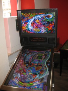
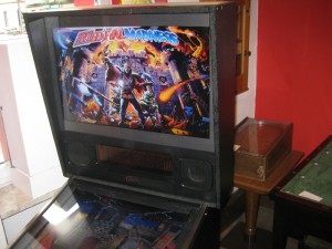
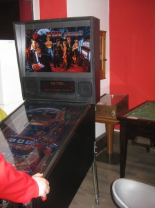
today we presented the Virtual Pinball at the www.flippermuseum.eu

Here you can see some pictures:

cirqus_voltaire

frontdoor

mediecalmadness

whodunnit2

Beta Finalisation

Freitag, Mai 14th, 2010

The wiring is done.
Using a InferfaceASD for Keyboard support. And the nanotech MotionKit. Having trouble with nudging…. Later…. I am using a big relais for „forcefeedback“ powered by 24V and using the contacts of the relais for the InterfaceASD.
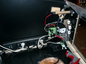
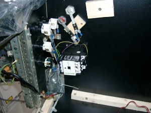
wiring

wiring2

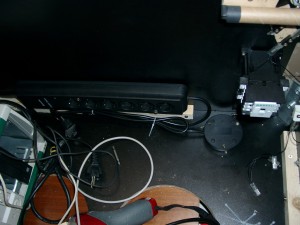
A plugbox with switch for powering up the system:

powersupply

The Pinball Cabinet is around 10cm shorter as an original. So I have to cut the siderails:

siderails

siderails1

To cover the edges of the LCD i am using this here:

corner_edge

First complete look

complete1

Forcefeedback

Dienstag, Mai 11th, 2010

Here you can see the „forcefeedback“ Relais.

I will use two, one for the left finger and one for the right finger.

forcefeedback

Button Upgrade, edge painting

Dienstag, Mai 11th, 2010

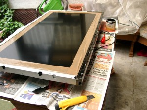
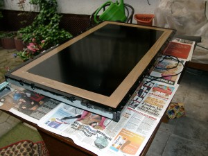
I removed the 42Zoll Display for painting the edge:
painting42_1

painting42_2

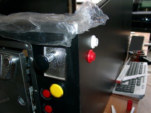
And some Button upgrade for left and right flipper fingers and a Button for Launch Button for the Flipper without a „analog“ plunger.

buttonupgrade

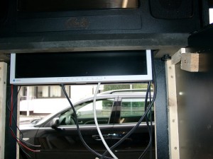
I used two scews left and right of the backglass to put it together

dmd_screen_mounted