Hi Folks,
thanks to an inspiration of BedroomNinja talking about a more PC-Engine like Tapto Reader 3D Printing Design – my idea was born to make the ultimative Perfect Tapto Mister Unit.
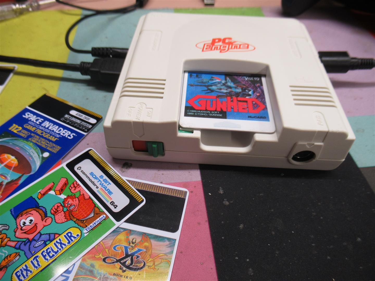
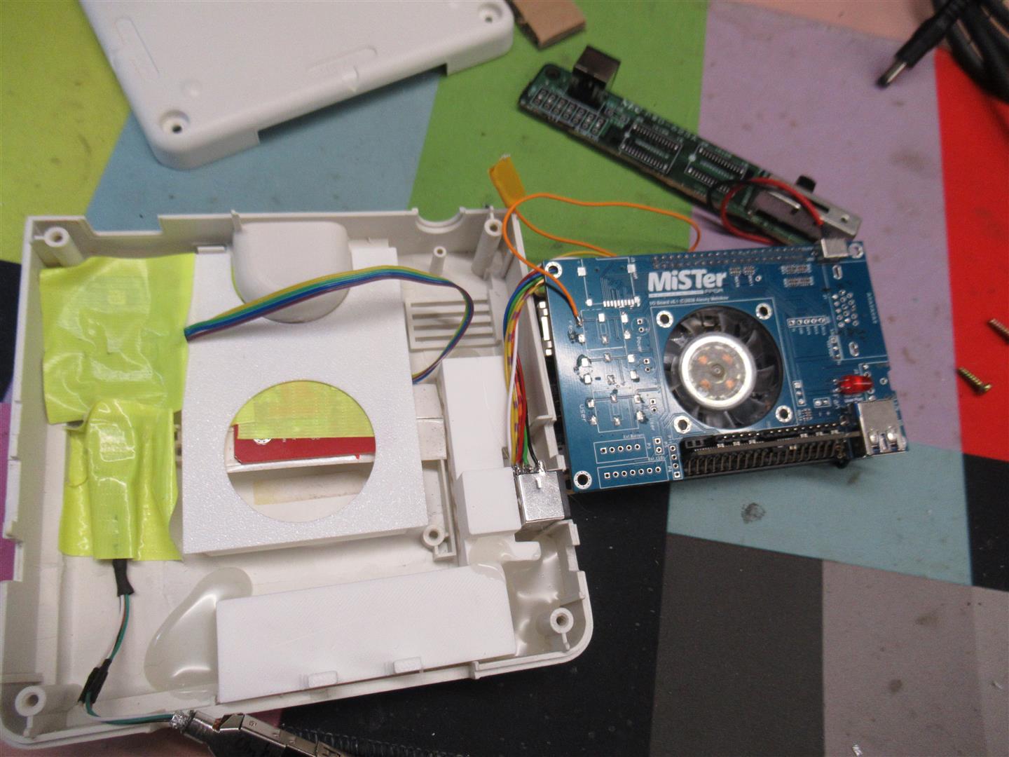
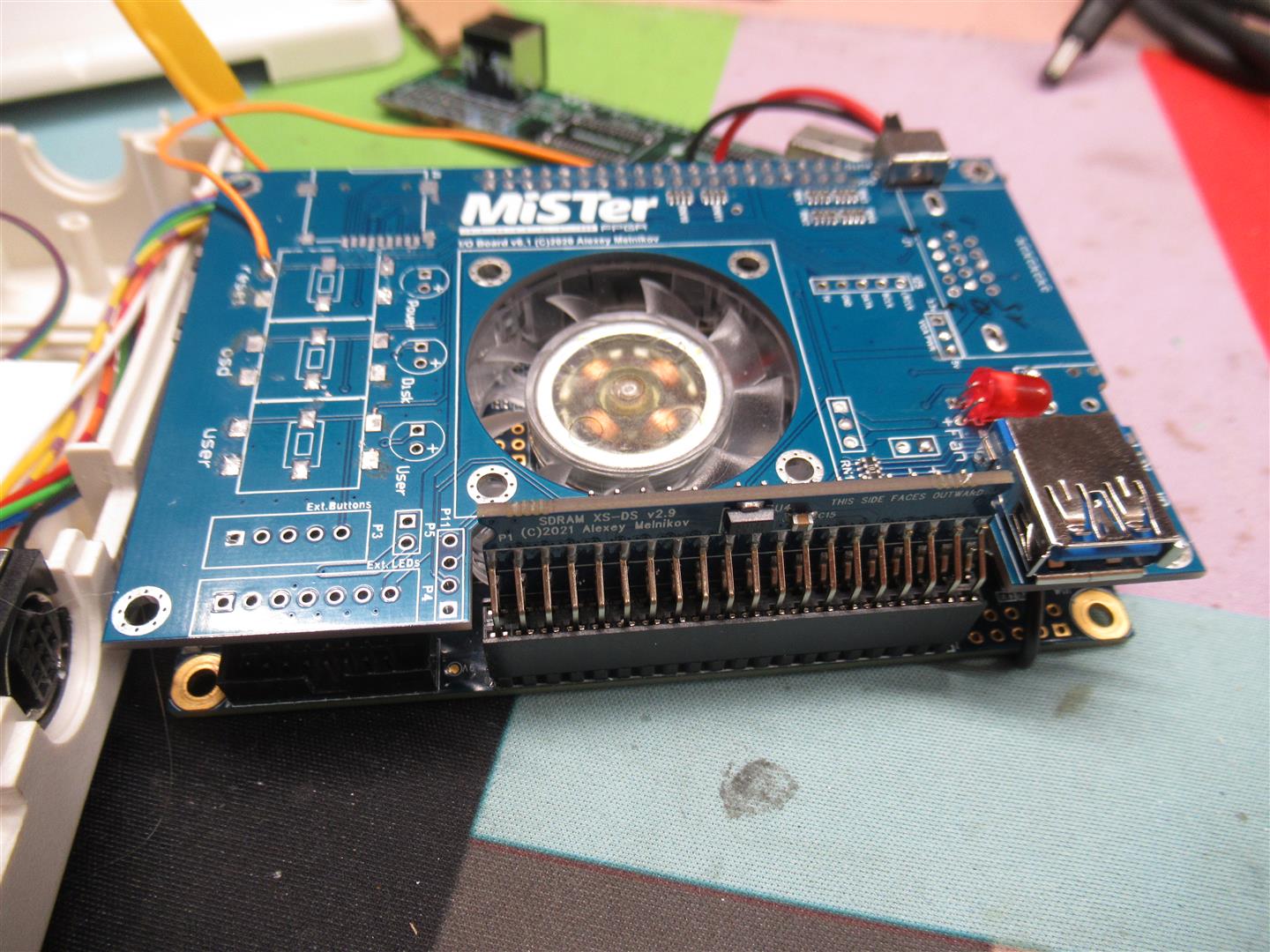
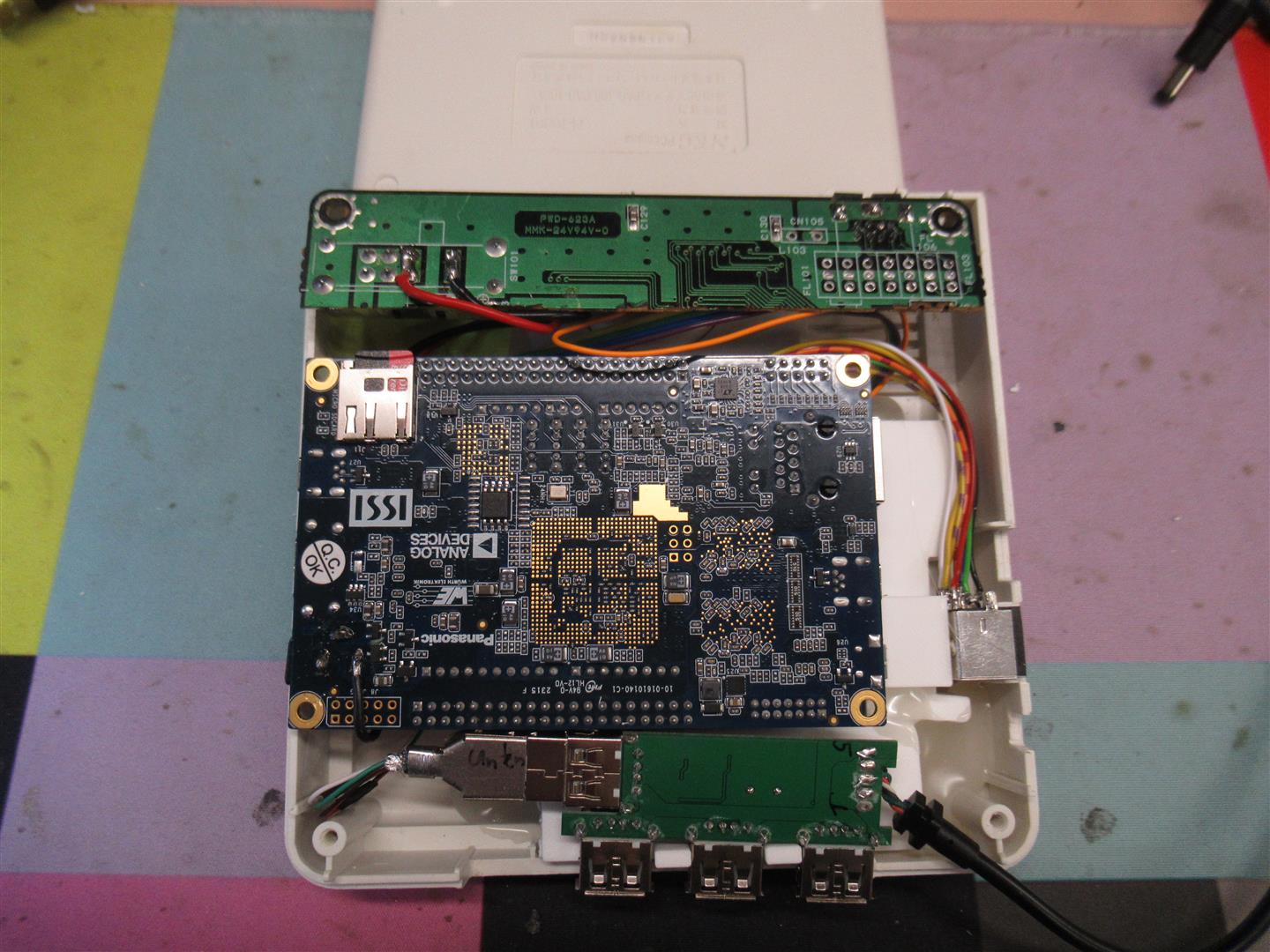
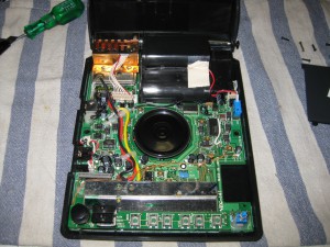
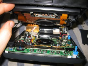
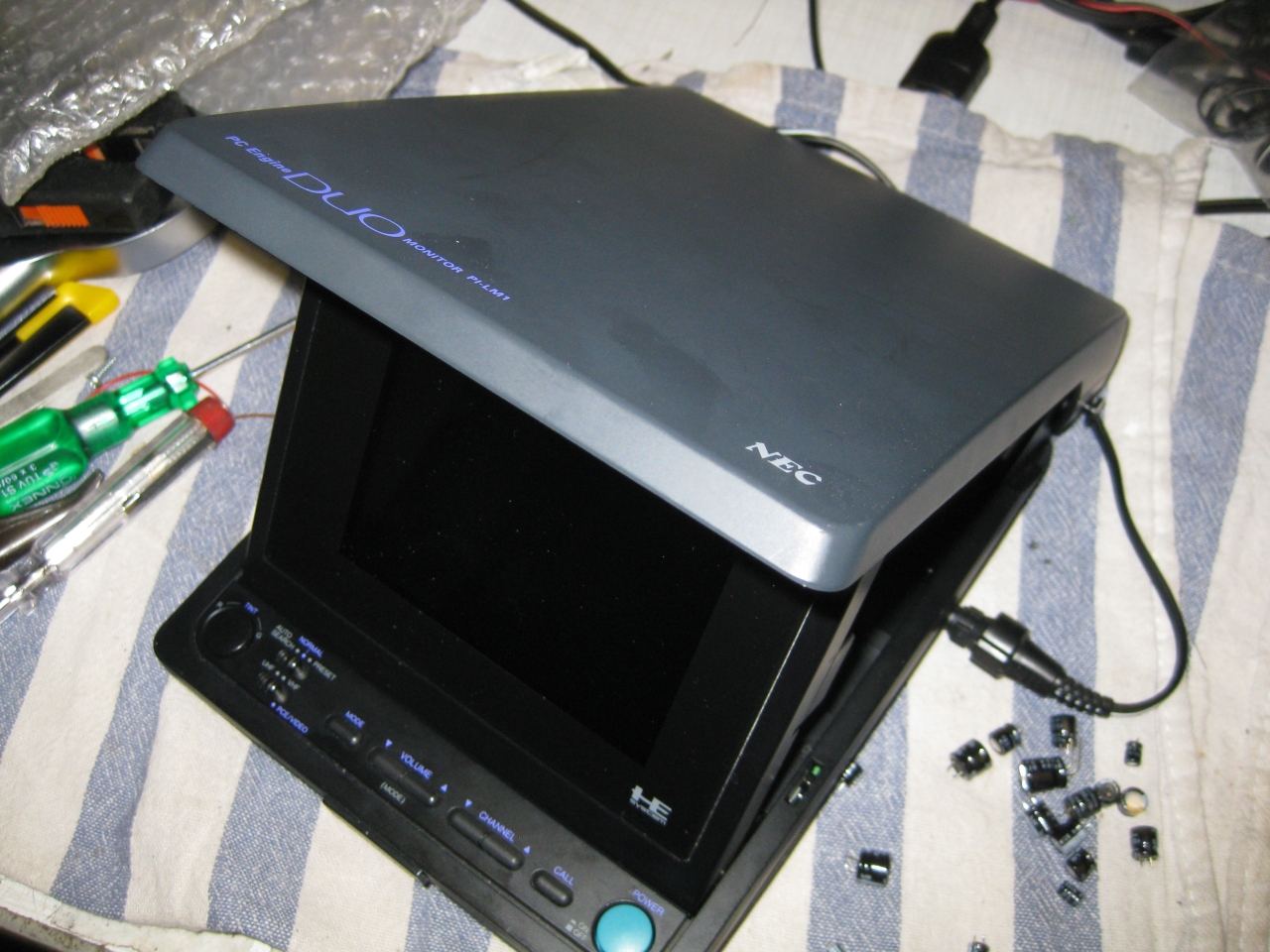
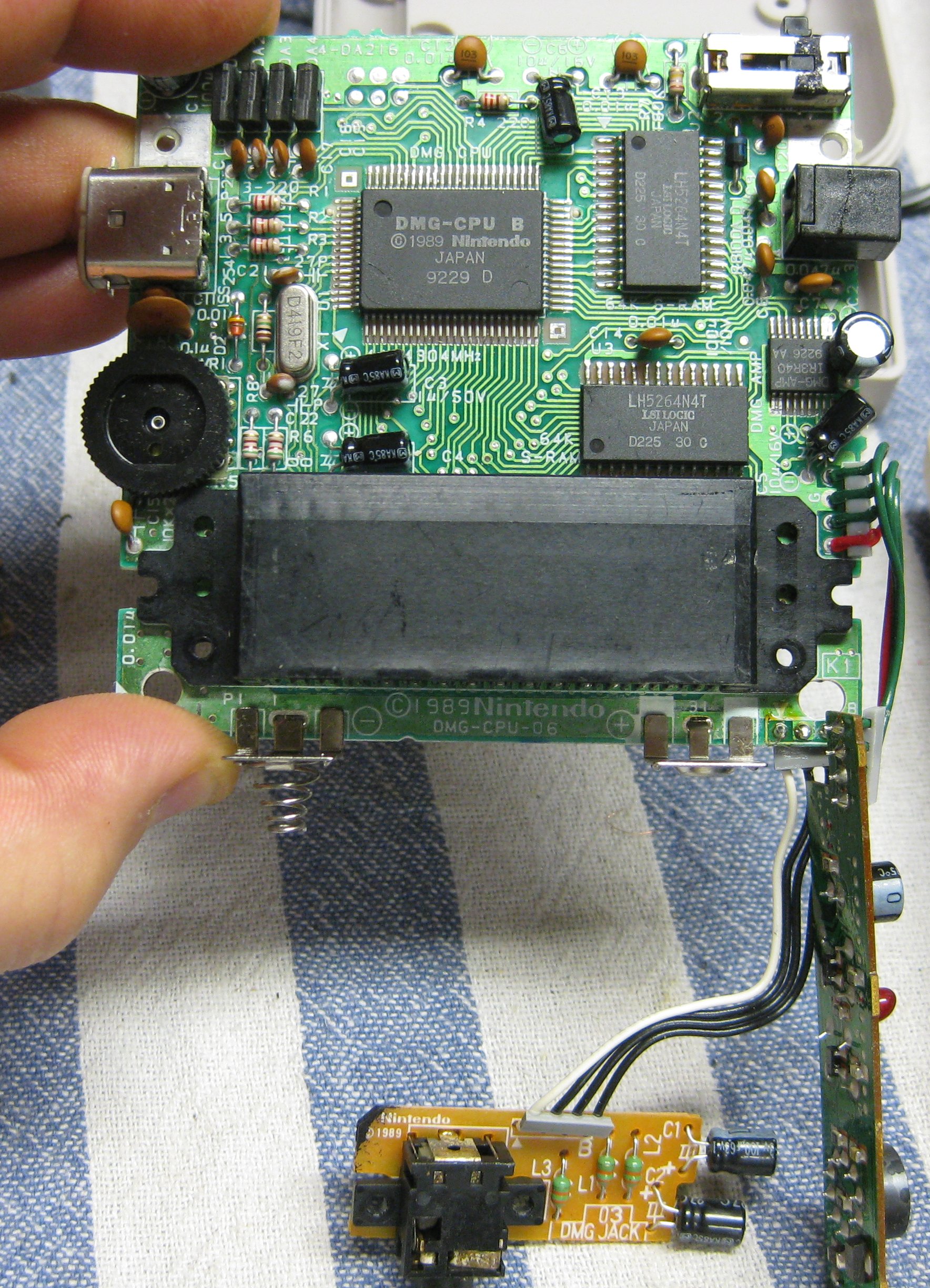
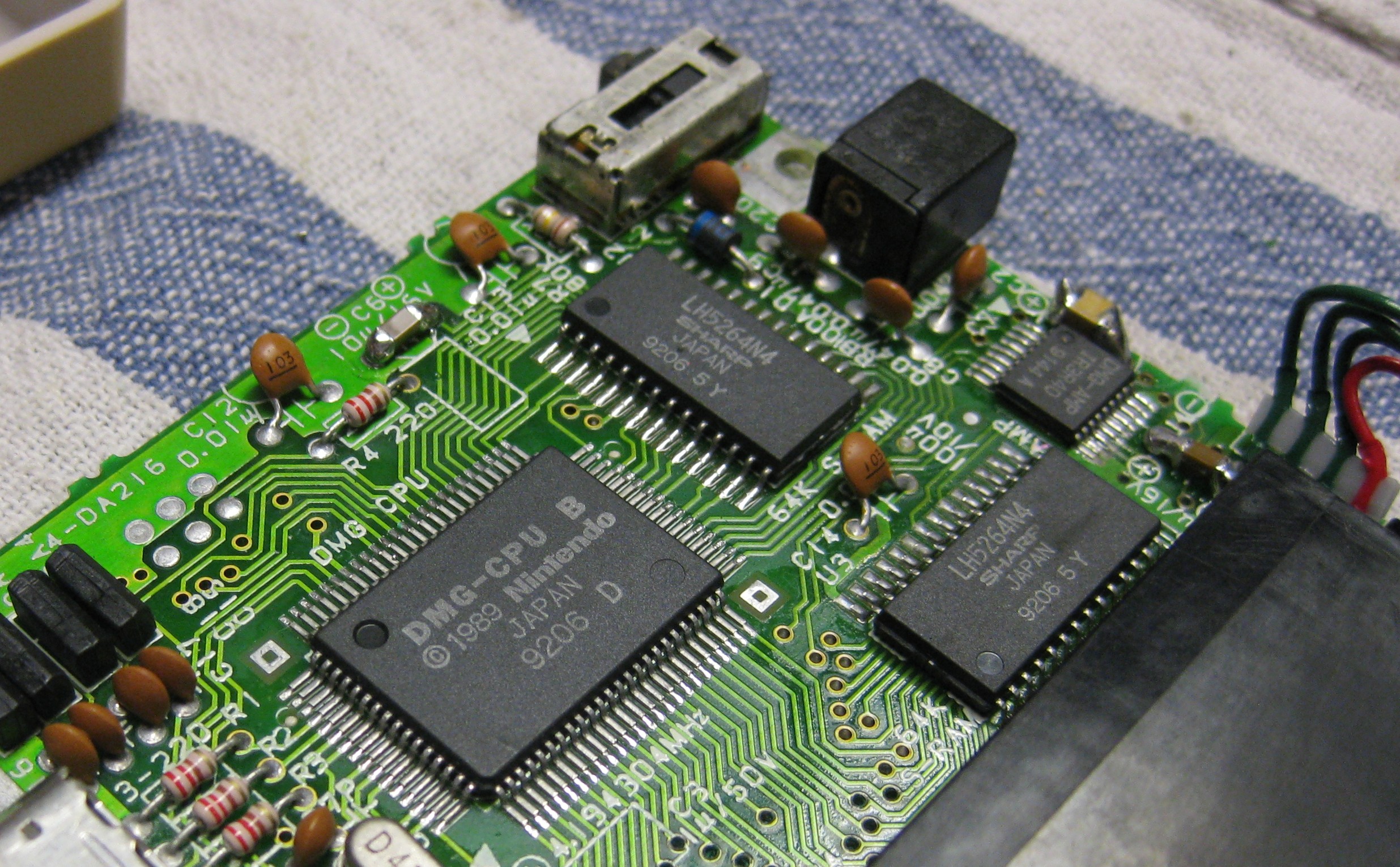
I used a broken original PC-Engine and put a DE10 Nano including a RGB-Analog Board into it.
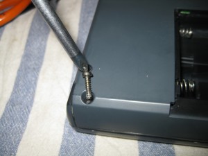
After some triming and some 3D printed peaces it fits into a PC-Engine.
In between of the I/O board and the DE10 Nano I put a Fan for cooling.
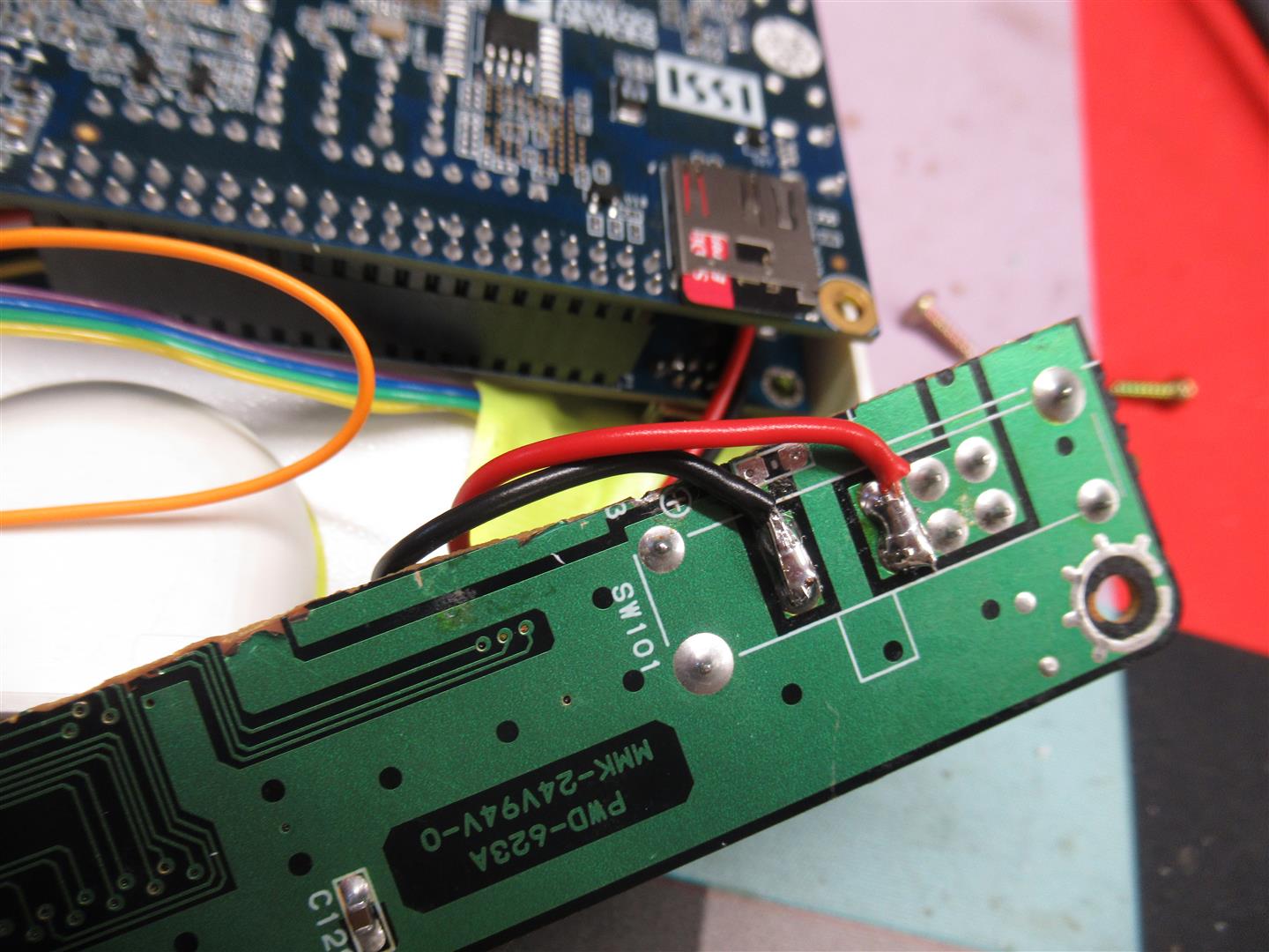
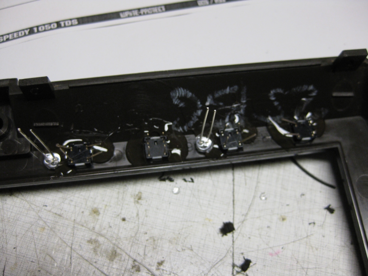
I ripped of some parts of the Analog I/O Board used parts from the original PC Engine PCB for power Button and the PC-Engine Controller Port (waiting for a snac adapter).
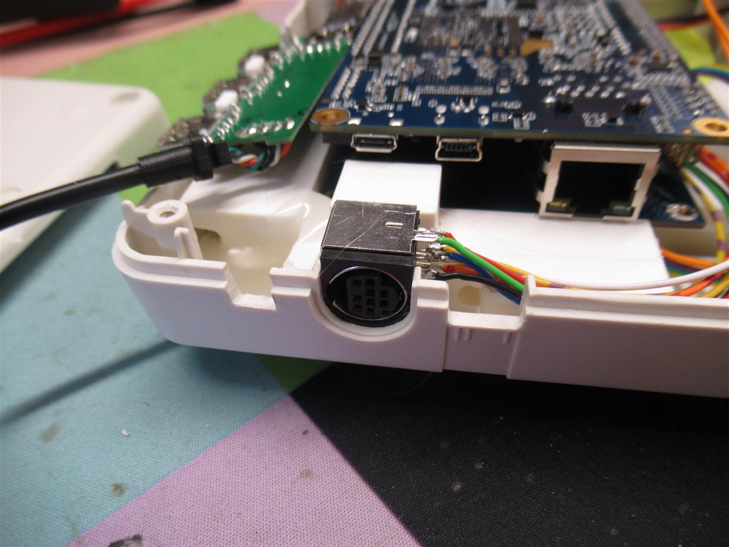
I used a Mini Din 8pin SMD2 Pin Compatible Port for analog RGB-Output.
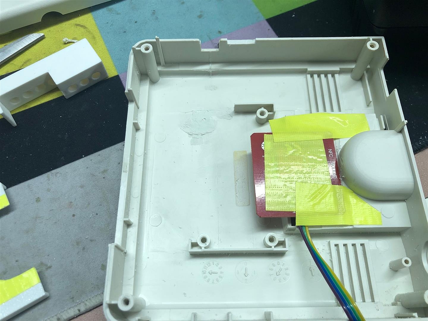
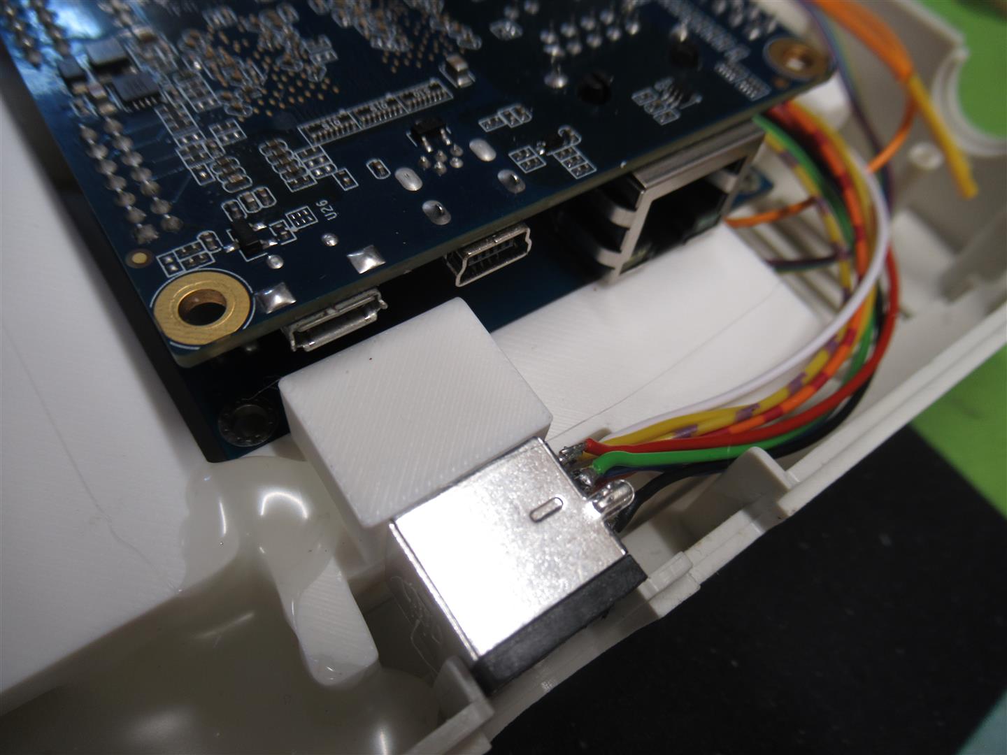
Put a 4 Port OTG USB Hub inside. a tapto Reader and voila.
Here we have it: One to rule and play them all ![]()
For reference and thanks for the great tapto Project!
It is a quick and „dirty“ hack. But from the outside it looks great and is fitting for my application.
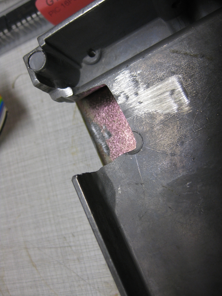
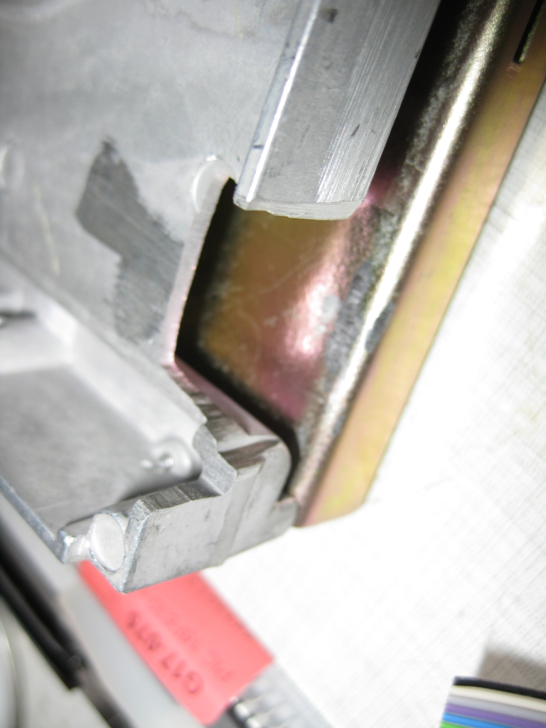
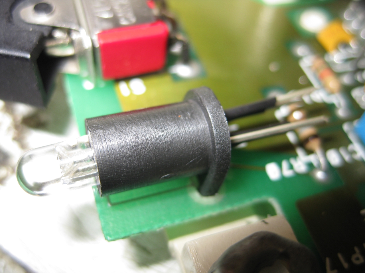
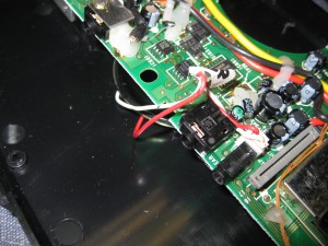
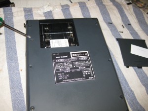
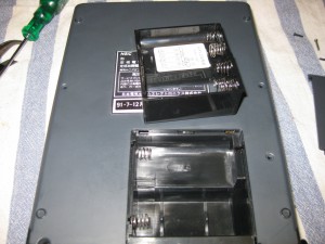
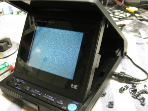
Here are some pics from inside for inspiration…