I am in search for a nice Harddisc Case in white, but I didn’t find any nice looking case…
After this I decided to put a 3,5Zoll Sata Harddisc into a broken Wii.
I am planing to use the original Power Supply and the original USB Connectors.
")
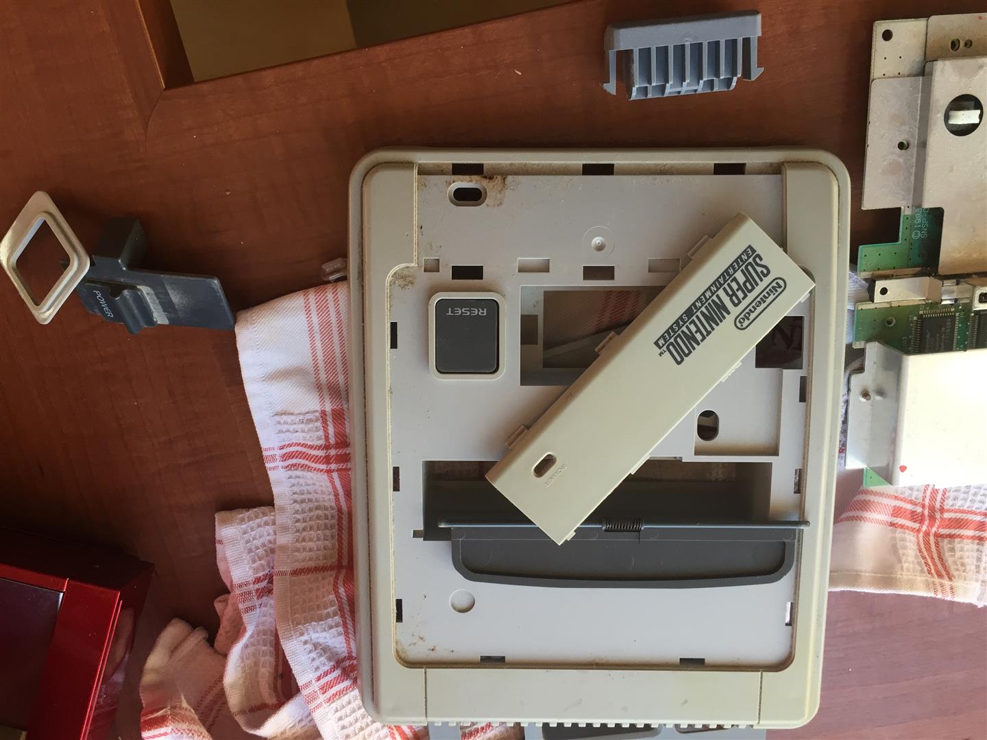
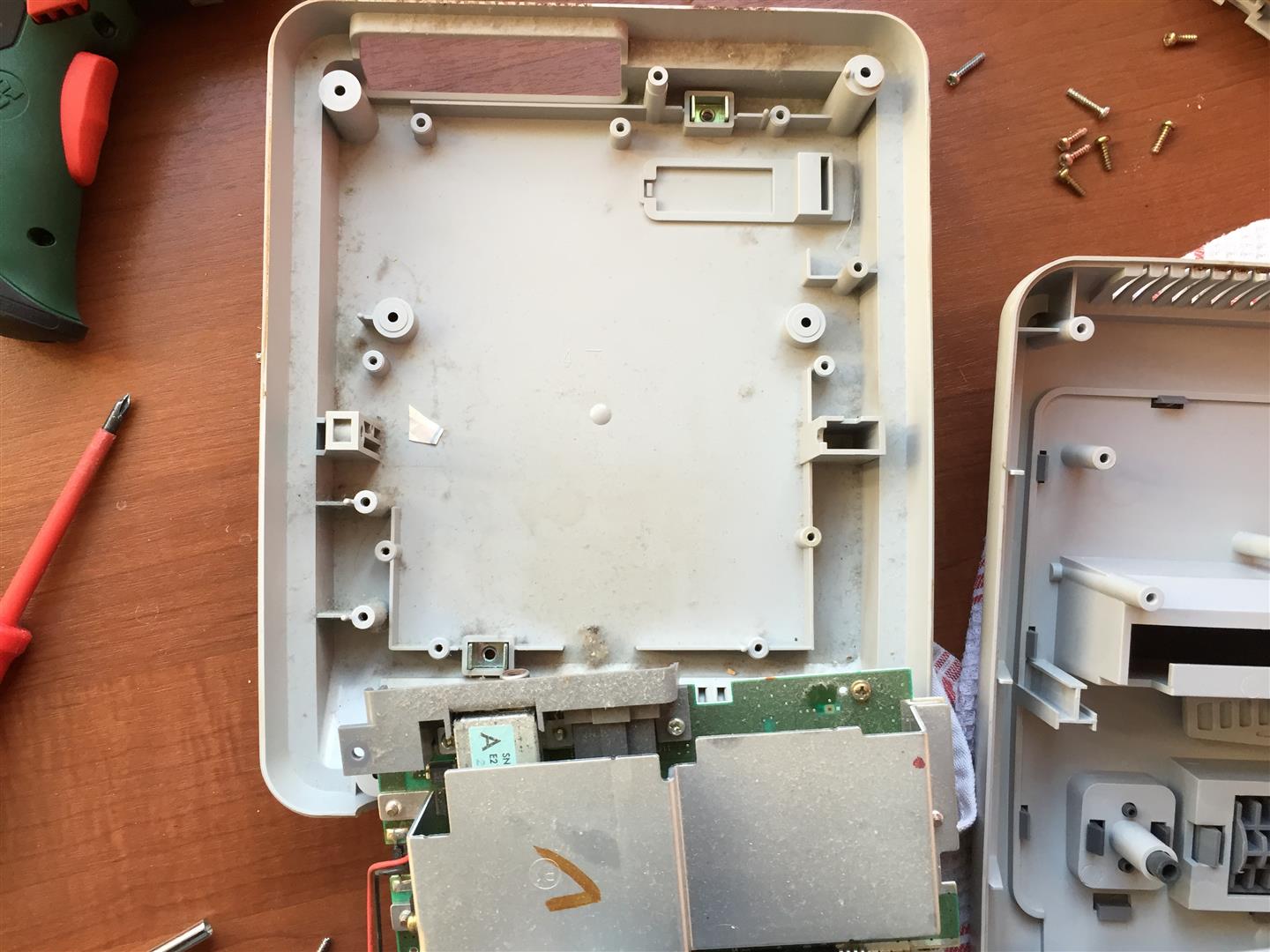
I opened the wii and removed all until you only have the main PCB inside
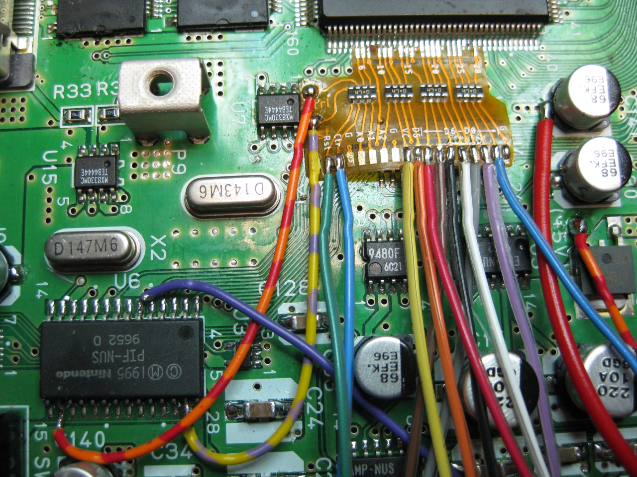
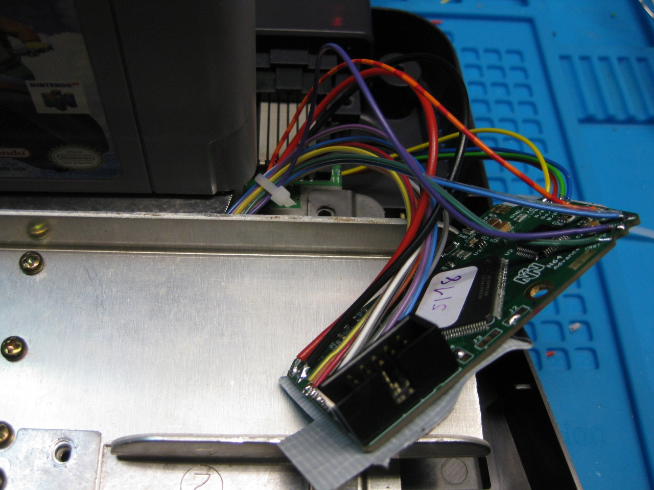
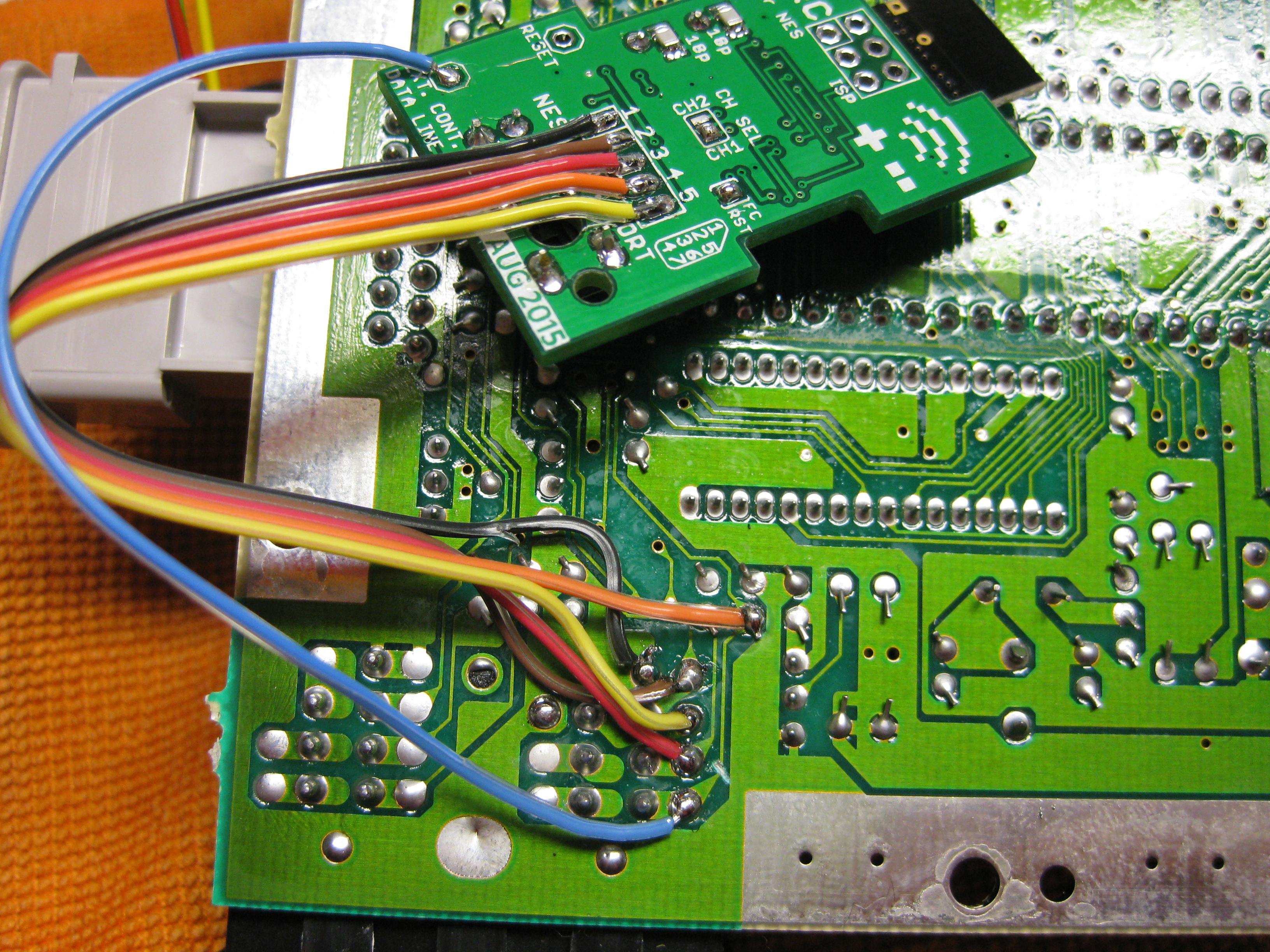
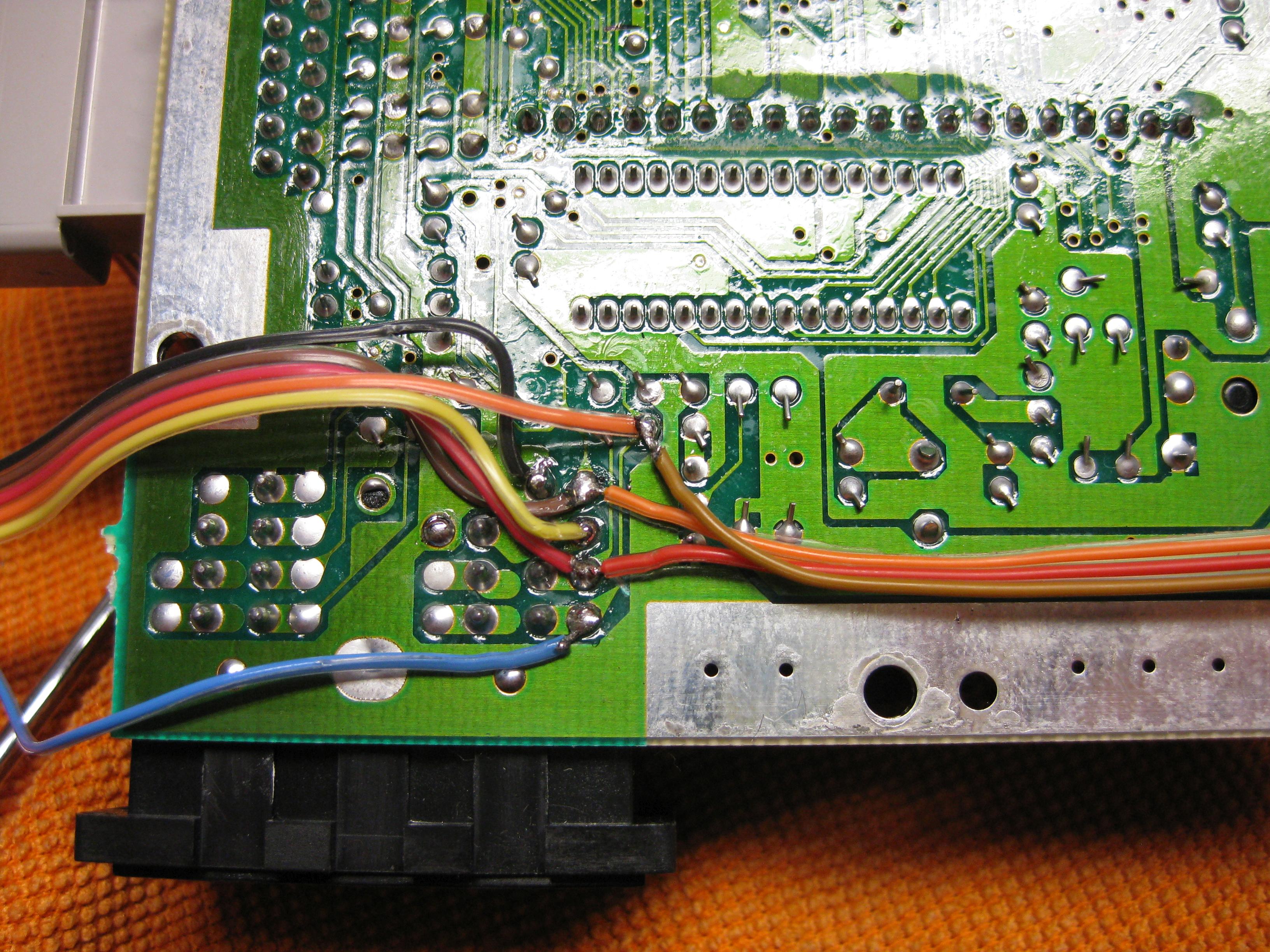
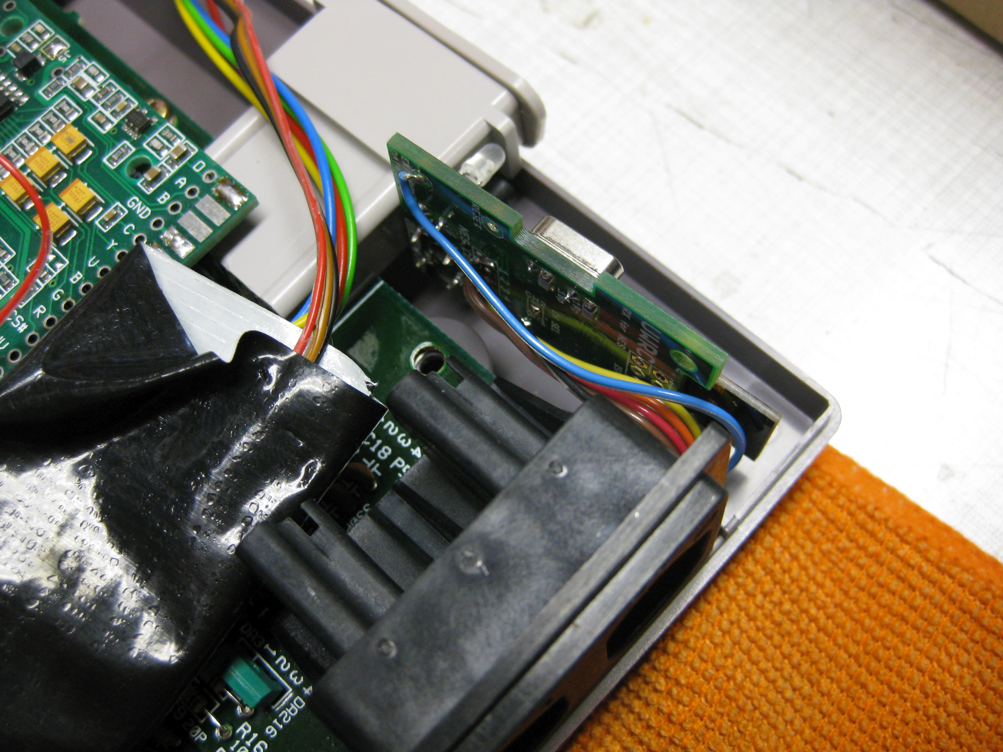
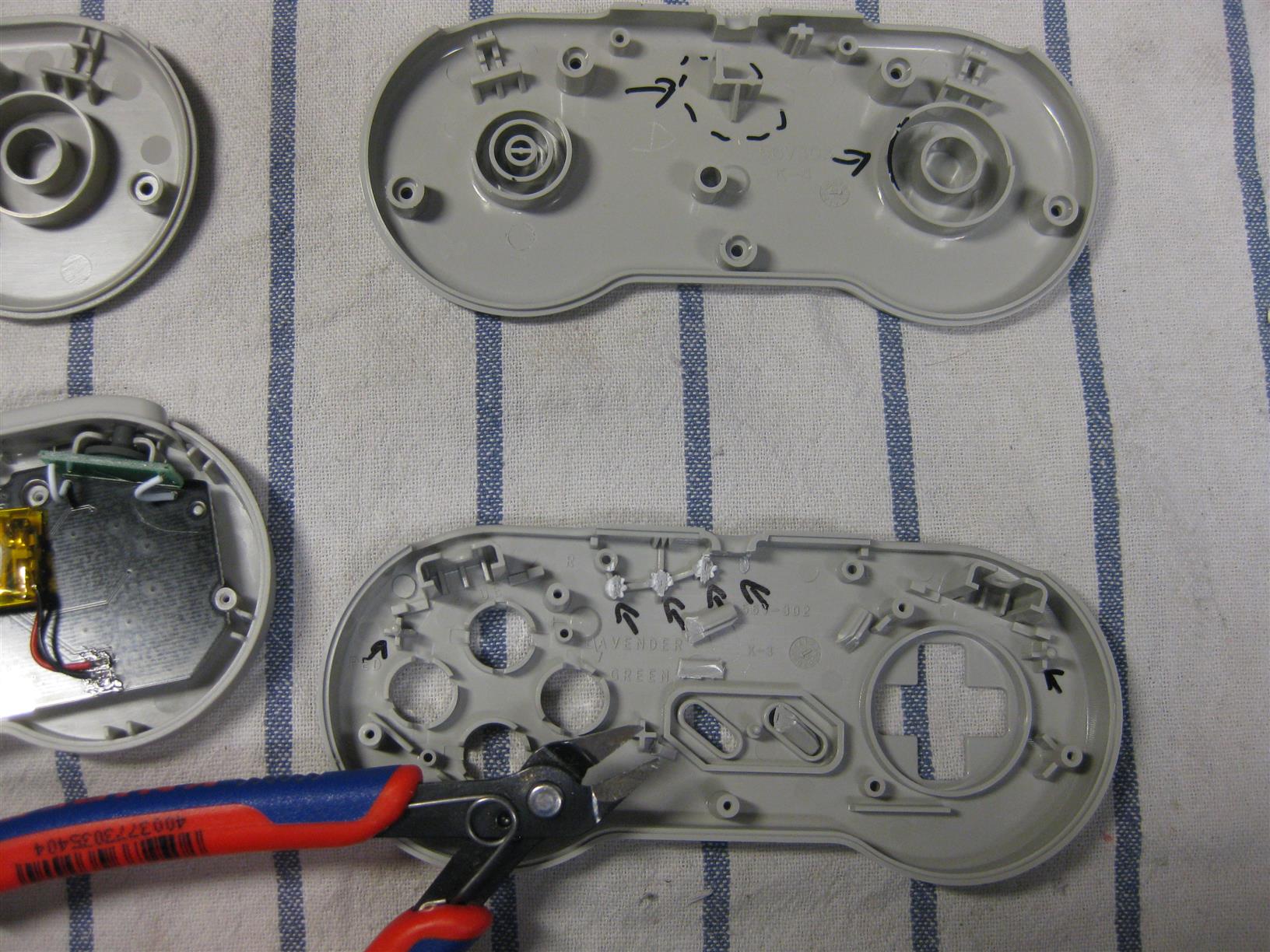
I removed to parts (red marked) to disable the USB Wires into the mainboard and connected the USB Cables from the USB/Sata Connector to the onbaord USB Port
")
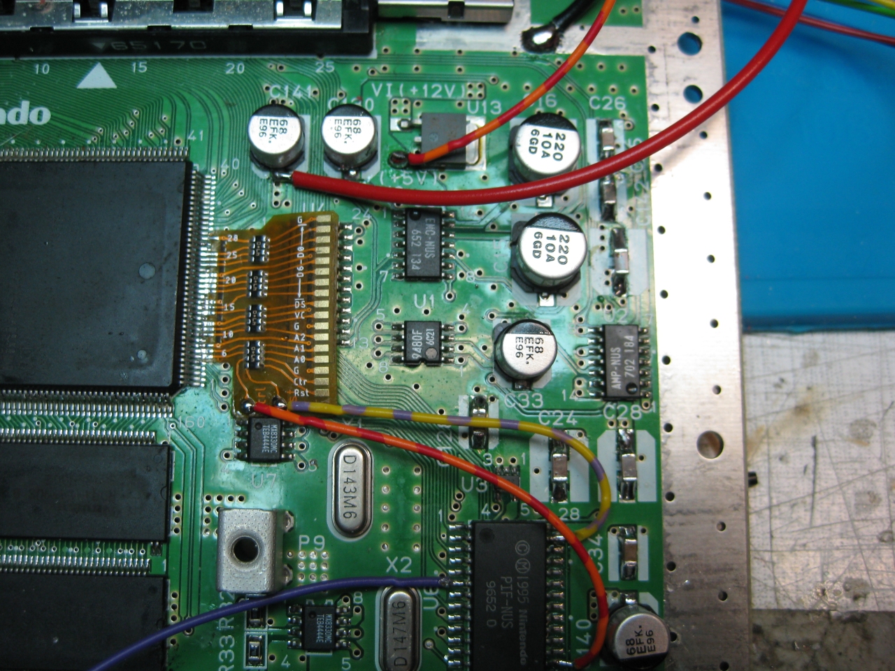
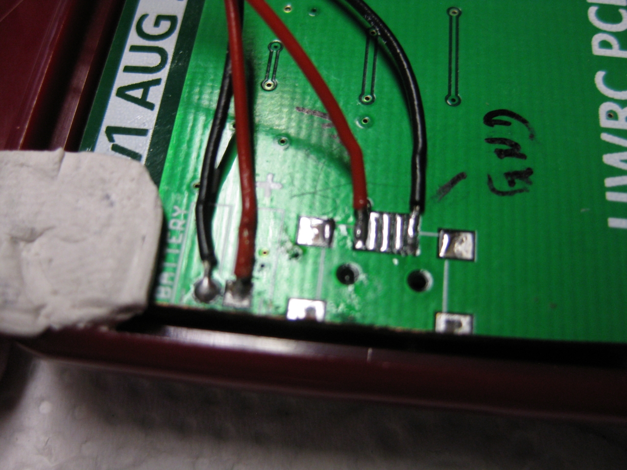
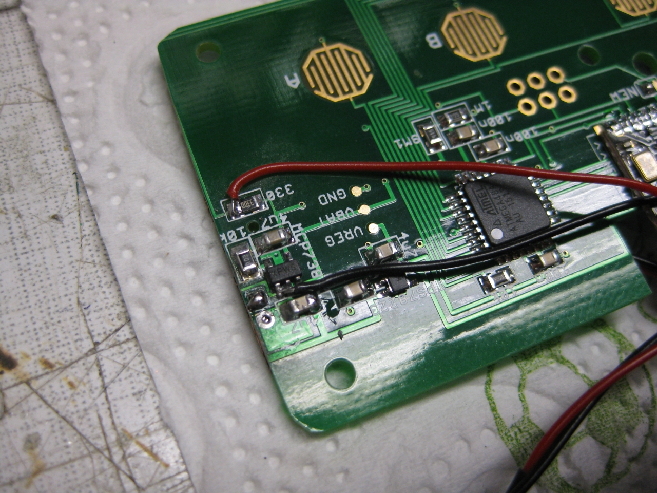
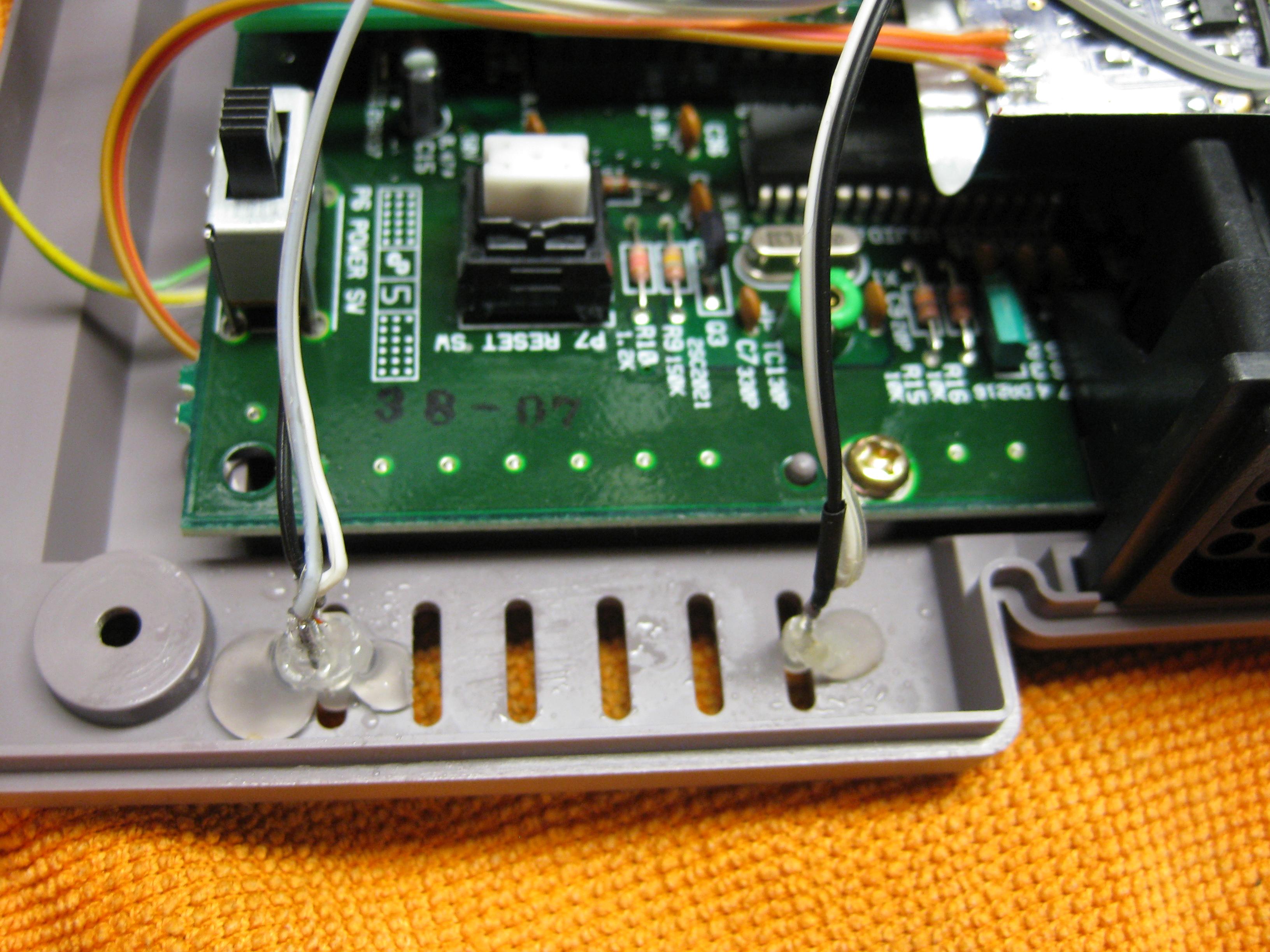
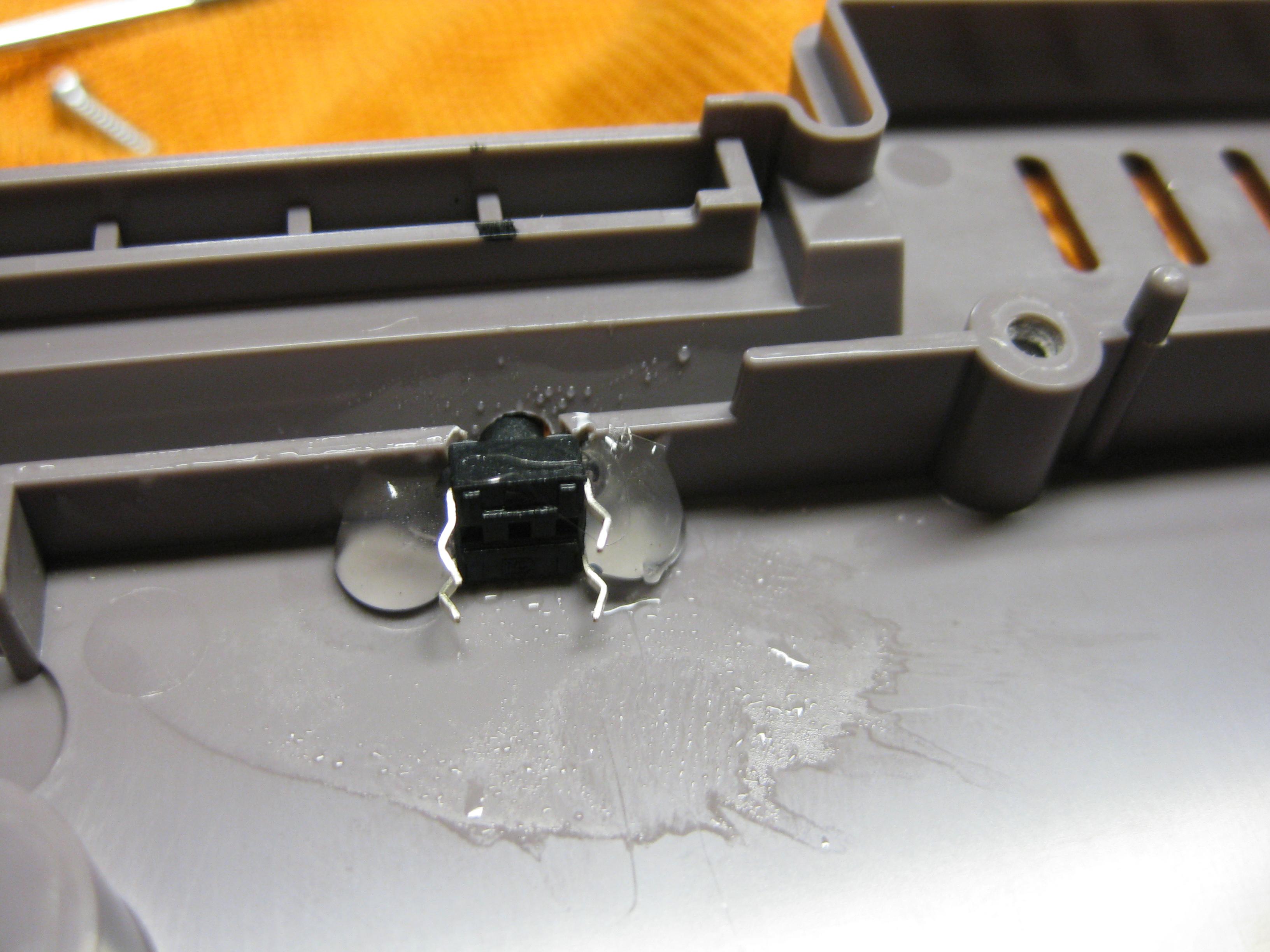
The power is taken from the Top Site of the mainbaord. Here I have to remove the original Fuse (red marked) to avoid getting any voltage to the mainboard.
You can get 12V to power up harddisc from the right site of the fuse.
GND is found at the edge of the mainboard.
I placed a standard 7805 voltage regulator to get the 5V for the Harddisc
")
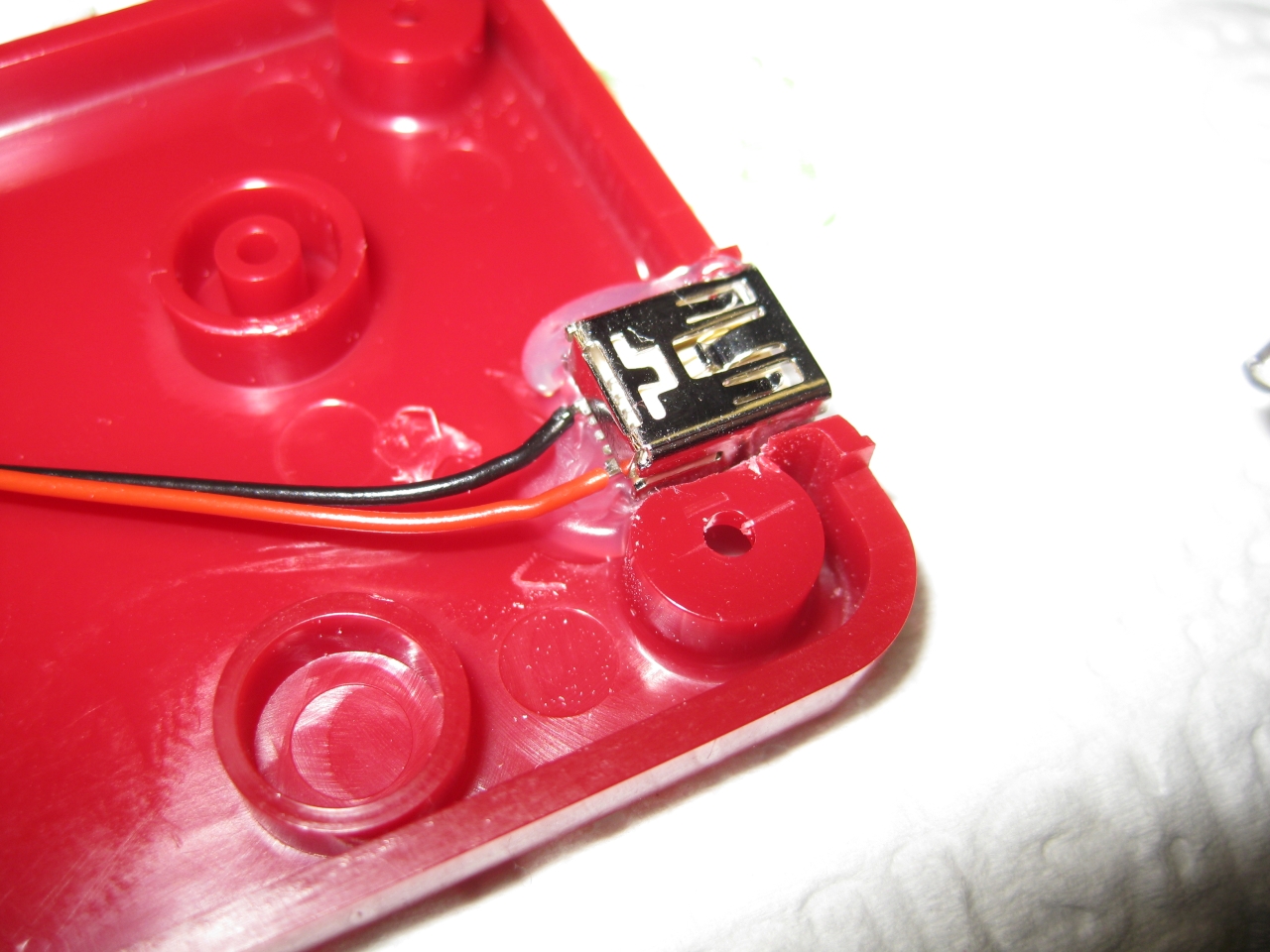
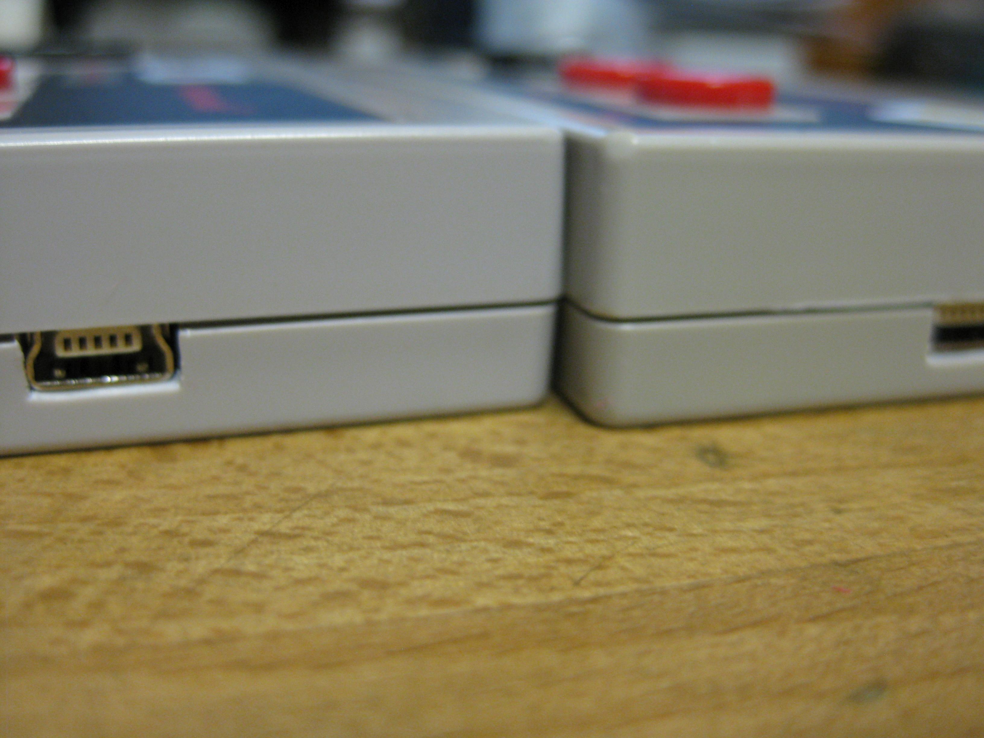
Here you can see original case of the used USB/Sata Connector
")
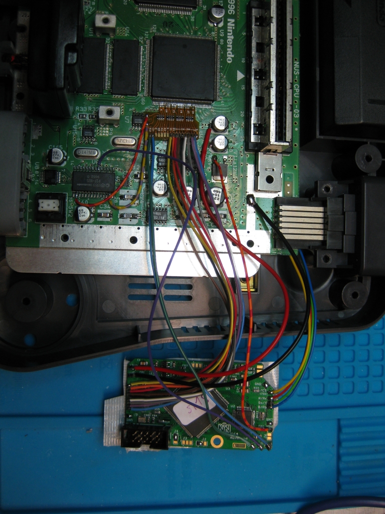
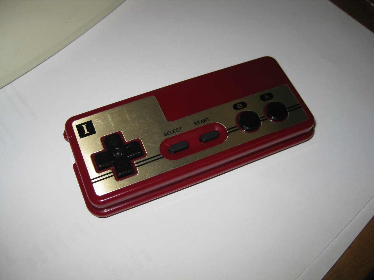
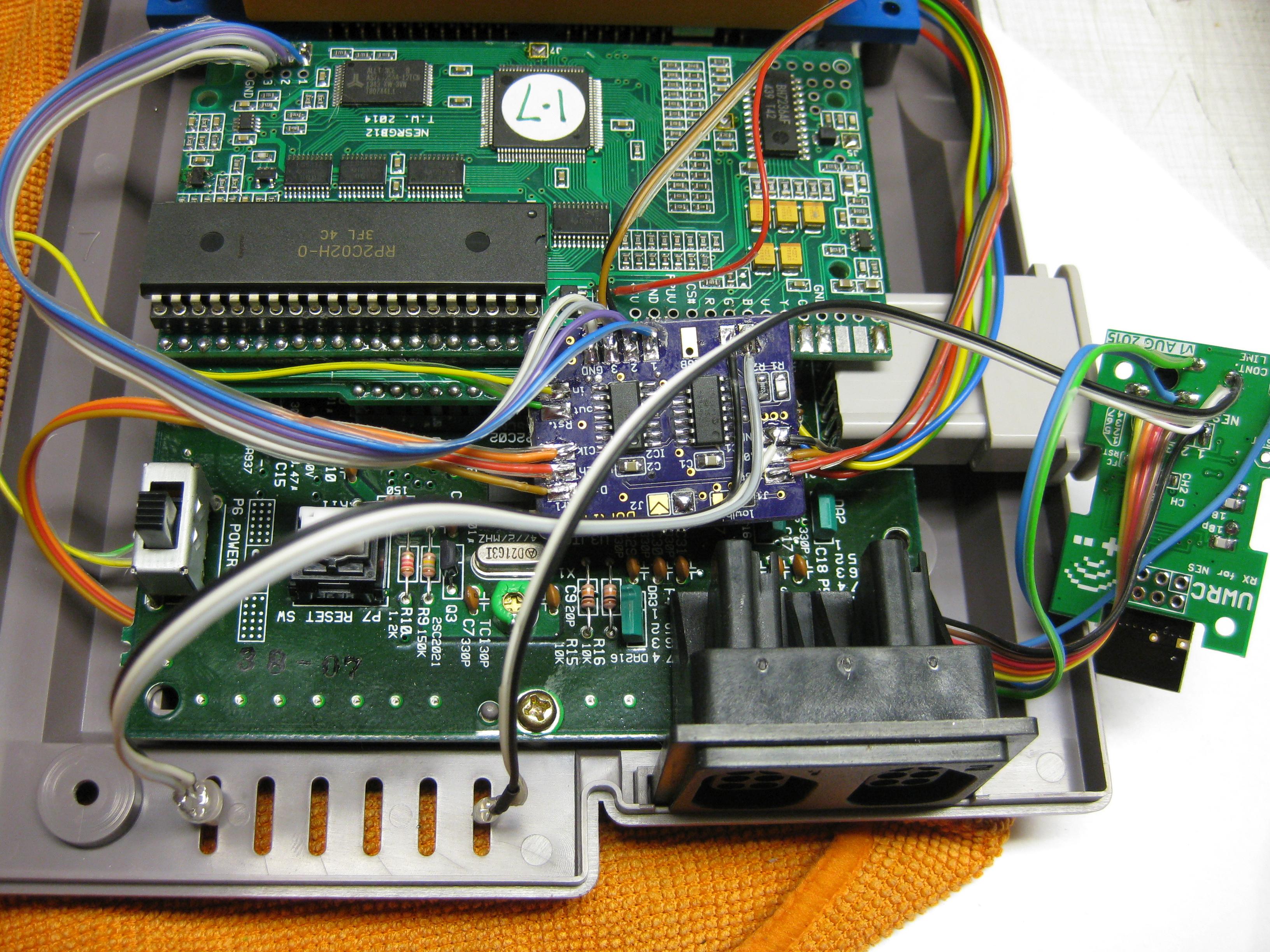
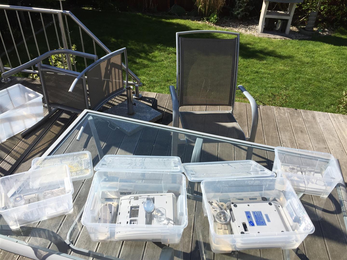
all together
")
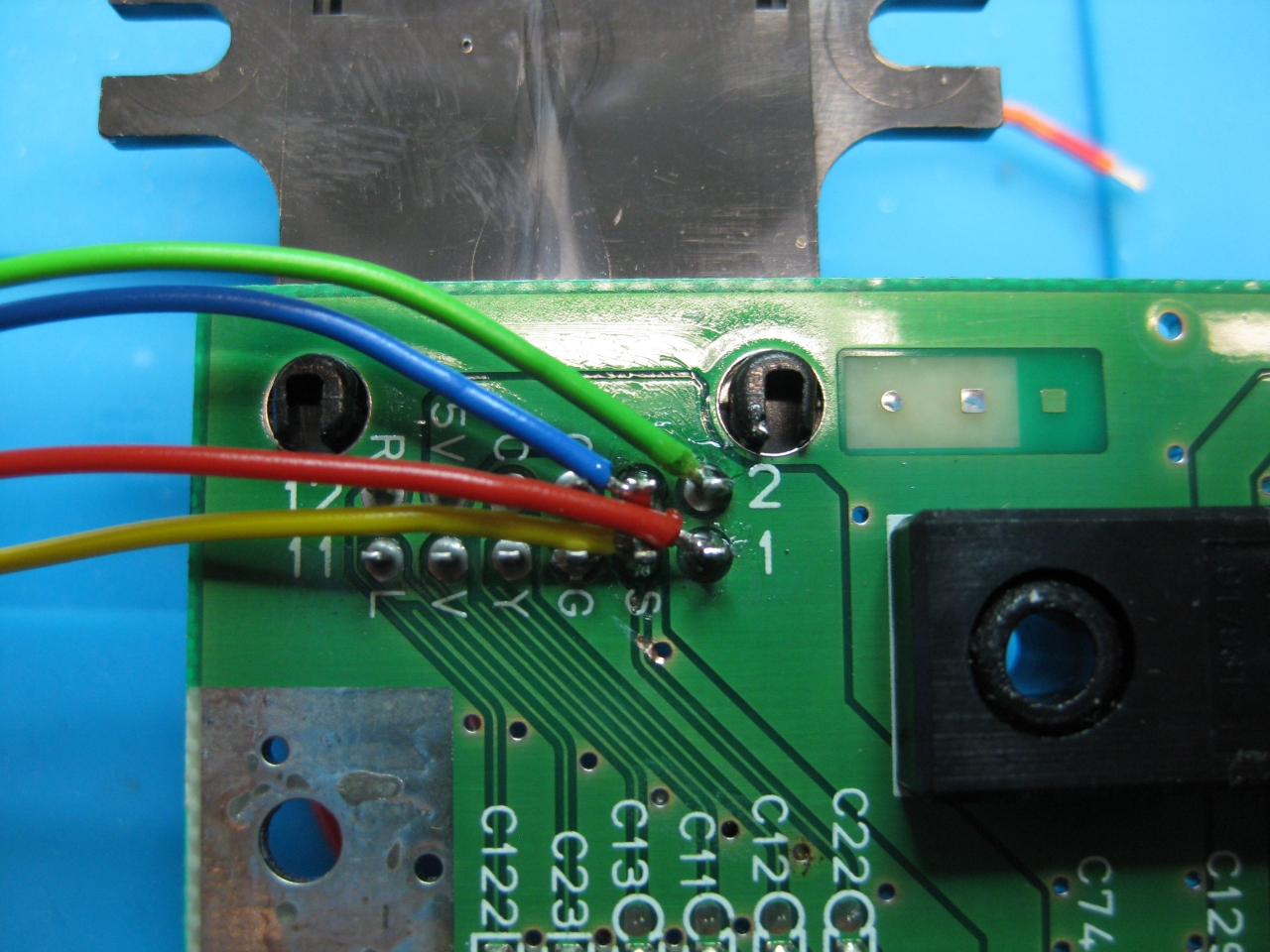
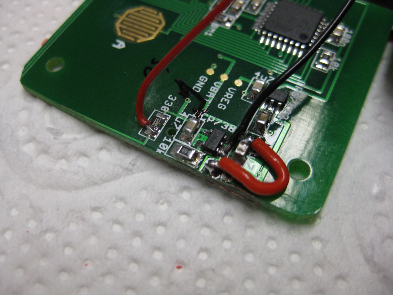
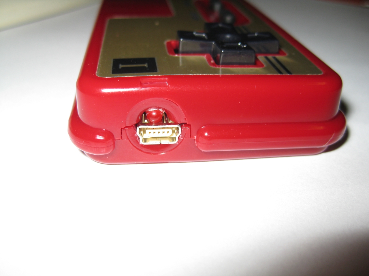
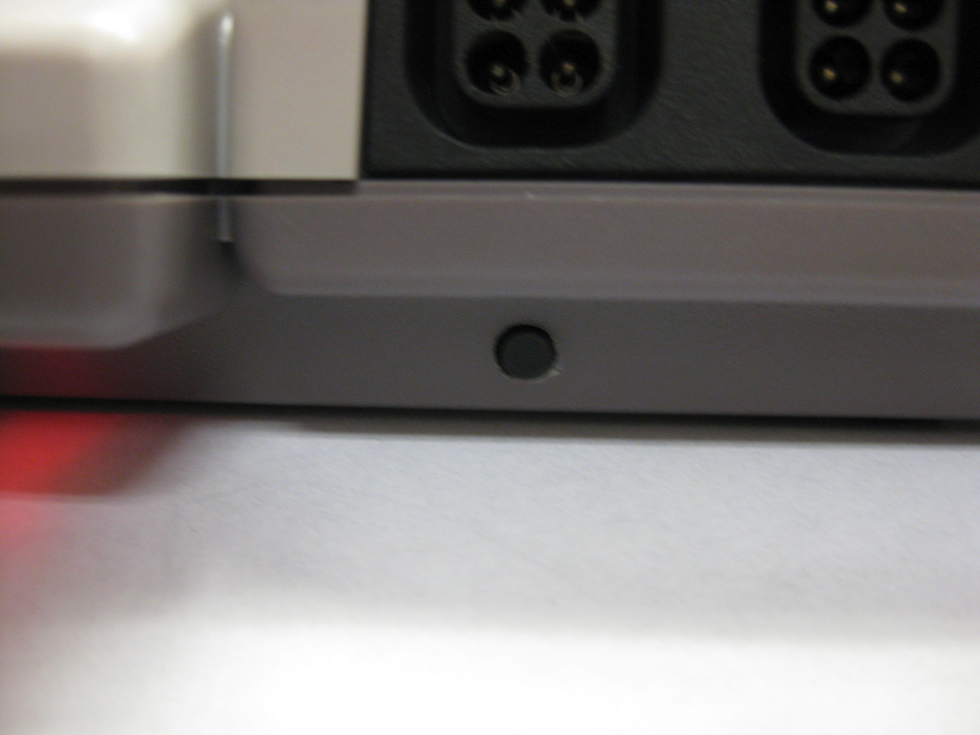
I extended the power Led of the USB/Sata Adapter to the original power LED of the wii
")
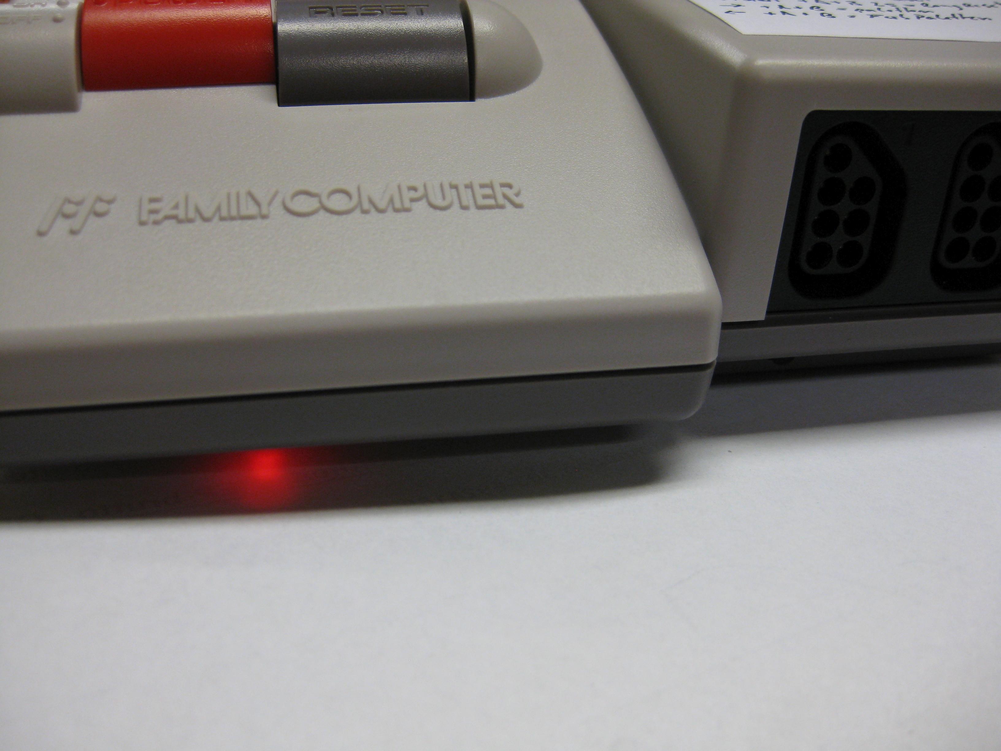
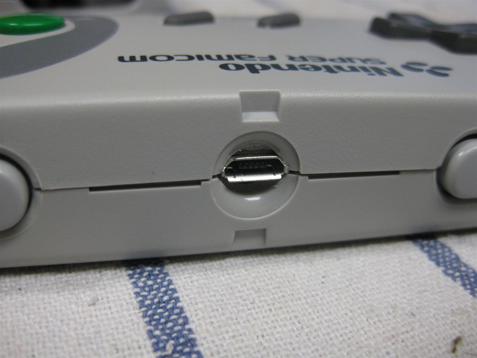
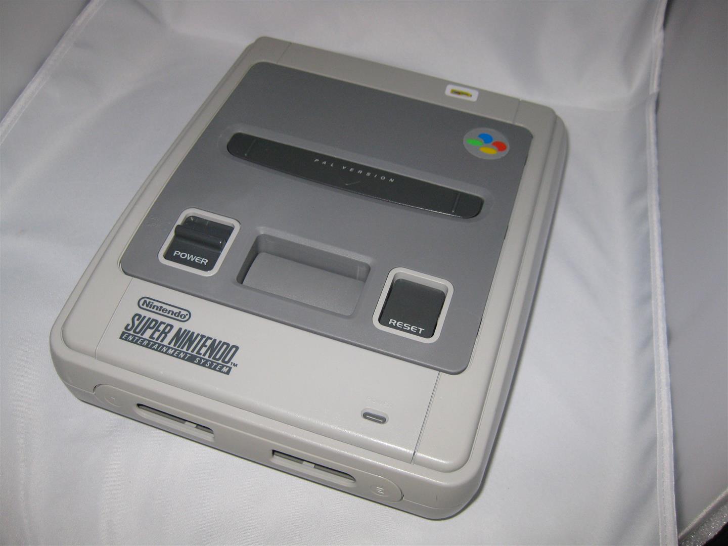
And here you can see the final backsite with connectors
")


")
")
")
")
")
")
")
")
")
")
")
")
")
")
")
")
")
")