Archive for Oktober, 2009

LCD work for Pinball

Mittwoch, Oktober 28th, 2009

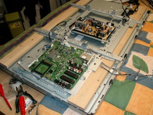
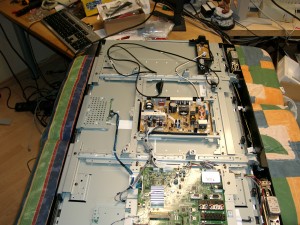
After a view weeks I managed to remove the cover.

But after removing the PCBs/electronics are loose. They must be re-attached in a way.

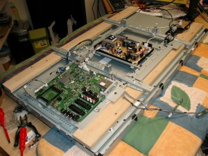
lcd_backsite attachment of electronic1

I take some wood for reattachment

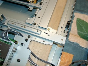
lcd_backsite3

lcd_backsite4

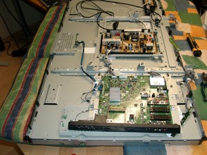
first view without cover

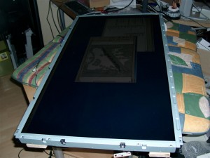
turning back to have the first look of the native display

Now its time for wood stuff

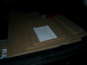
mdf_for_pinball

and the widelockbar

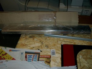
widelockbar

AimTrak for Beretta gun

Mittwoch, Oktober 21st, 2009

I like Beretta Guns, but until now there was no way to use them with Arcade Cabs.

A month ago ultimarc give us a new product called AimTrak. It is like the Wii Remote with a Camera inside and a Sensorbar at the top of screen.

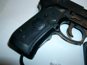
We have some good old BerettaGuns left for XBOX1 and I ripped of original stuff to make them working with AimTrak and my Arcade Cab.

The procedure tooks 3-4h of work *puh*

Here you can find the gun

Here you can find the AimTrak

Little Video

I tried it at my arcade cabinet with a crt put the senorsar in top of the screen and it works absolutly *great* Fun ONLY

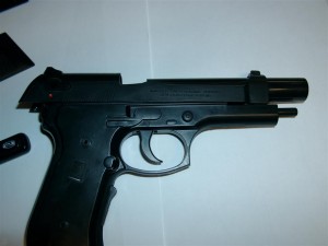
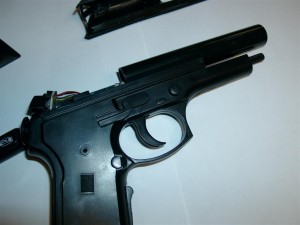
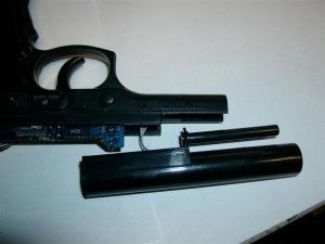
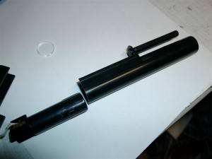
Here are some pictures of the progress:
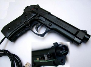
aimtrak_teaser640x400

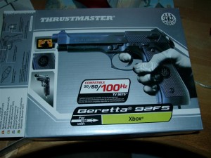
good old Thrustmaster Beretta Gun

good old Thrustmaster Beretta Gun

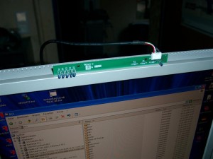
"Sensorbar"

"Sensorbar"

The Sensorbar only need 5V powersupply. So it is connected to a USB Port for powering.
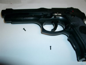
First 2 screws

First 2 screws

Opening Part is easy

First 2 screws
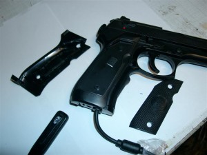
First 2 screws
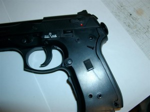
First 2 screws

First 2 screws

First 2 screws

First 2 screws

good position of the B-Button downside
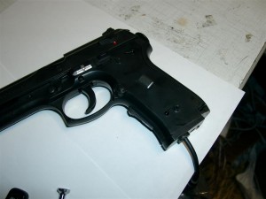
First 2 screws
First 2 screws
First 2 screws
First 2 screws
First 2 screws

First 2 screws

First 2 screws

First 2 screws

First 2 screws

First 2 screws

original photoeye
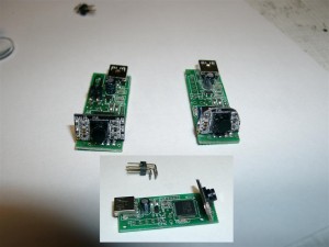
aimtrak11

for fitting into the beretta it was neccacary to reduce the size of the AimTrak
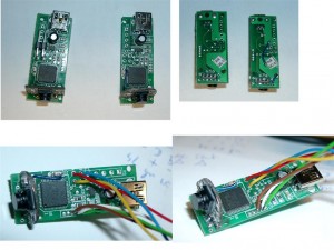
comparing original size and reduced / Wires

comparing original size and reduced / Wires

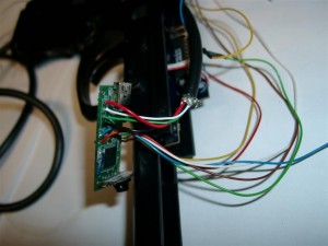
And do some rewiring

Wiring including 5 Buttons.

Fire, Reload B, Reload A, back, and start
The original AimTrak can use 2 Buttons with a connector.

There are 5 more if you can solder
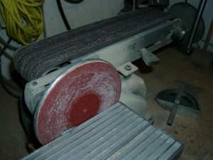
I used this device to cut off the pcb
I used this device to cut off the pcb

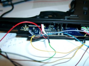
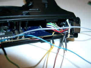
rewiring buttons a,b @ side of gun

rewiring buttons a,b @ side of gun

Wiring Button A, B
First 2 screws

First 2 screws

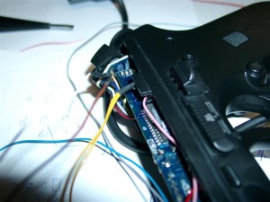
Wiring back and Start for use of Coins, and Start/Continue
First 2 screws
First 2 screws

First 2 screws

First 2 screws

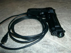
I make use of a 3m USB Cable and solderd it directly to the AimTrak
First 2 screws

First 2 screws

Here we go

First 2 screws

First 2 screws

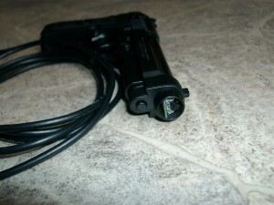
In front you can see the new „eye“

UPCB Playstation Cable

Montag, Oktober 19th, 2009

today I got my PSX Cable to work.

It is the 3rd extionscable I was using.

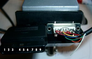
Dedicated Digital Playstion cable for UPCB

Console Function Color D-Sub Bridge Bridge Function Color
1 DATA brown 1 Low GND black
2 CMD orange 2 Low
3 7 to 9V white 3 Low
4 GND black 4 High
5 3,4V red 5 ATT yellow
6 ATT yellow 6 Low
7 CLK blue 7 Low
8 n/c 8 High VCC red
9 ACK Green 9
10 High
11 Low
12 CMD orange
13 ACK green
14 DATA brown
15 CLK blue

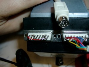
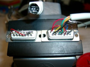
psx_plug

psx_wiring

Playstation

Playstation

upcb PC-Engine Cable trouble

Freitag, Oktober 16th, 2009

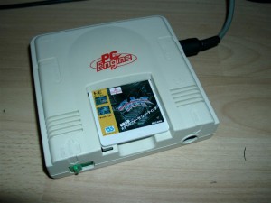
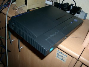
I currently trying a PC-Engine Cable but it didn’t work :-(

testing with: 2 differnt ucpb rev 2.1 Software 2.5 BP

Have checked both a white pce and a jap. Duo Engine.

white_engine

pce_duo

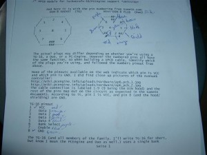
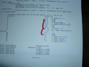
Here is the wiring

pce_minidin

Checked the VCC and Gnd with a Multimeter

pce_subd15

wiring2

wiring1

upcb GameCube Cable

Freitag, Oktober 16th, 2009

Usage (short Version)

Start: Stick is reported to D-pad only instead of both D-pad and left analog
Select: Stick is reported to left analog only instead of both D-pad and left analog
Strong+Forward: Smash Brother Basic mode
Fierce+Roundhouse: Smash Brothers Advance mode

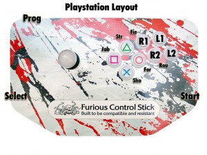
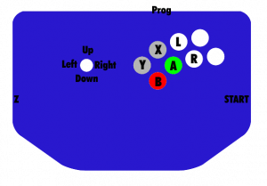
gamecubelayout

Pictures of Sub-D 15 pin male:

gamecube_cable1

Look into the Gamecube socket

Look into Gamecube socket


Pin Description GameCubePort

1 VCC 5V (green)

2 Data in (yellow)

3 GND (blue)

4 GND (red)

5 – (white)

6 3,43 V (black)

7 gnd (shield)

Sub D 15 pin

1 4 (GND) blue, red, shield

2 Low

3 Low

4 Low

5 High

6 Low

7 Low

8 1 (VCC 5V) green

______________________

9 NC –

10 High

11 High

12 NC –

13 NC –

14 2 (Data) yellow

15 High

USAGE in DETAIL

1. Default [automatic if you didn’t select any other mode] Stick gets reported to both right analog and d-pad. Select is Z, Start is start, and the layout is:
YXL
BAR
2. D-pad only [hold Start when plugging in.] Same as default, but the stick is only reported to the d-pad. Right analog always in neutral.
3. Analog only [hold Select when pluggin in.] Same as default, but the stick is only reported to the right analog stick. D-pad is always in neutral.
4. Smash Bros. Basic [hold Strong and Forward when plugging in.] 2,6 (A,X)Short is shield, Jab is A, Strong is B. Double tap a direction to dash. A+B+Direction does a smash attack using the C stick. Select is a dpad down taunt.
5. Smash Bros. Advanced [hold Fierce and Roundhouse when plugging in.] Buttons same as Smash Bros. Basic, but include forward as ‚jump‘ (just the Y button), fierce as ‚run‘, and roundhouse as ‚lock‘. Shield button will do a half-pull on the trigger with no click unless the ‚run‘ button is pressed as well; then it will do a full pull with click so you can choose which type of shield you need for hit recovery, L-cancelling, whatever. ‚run‘ button also makes the analog stick report as all of the way in the direction you want, instead of just a little bit, so you can choose to walk or run, tild or smash.’lock‘ button is for complex C-stick manuevers. It locks the analog stick where its at, and your stick will control the C-stick until you release the lock button. So, to do Peach’s floating b-air, jump and hold up on your stick, hold the lock button, and move the stick to the left or right.

uPCB Soldering

Mittwoch, Oktober 14th, 2009

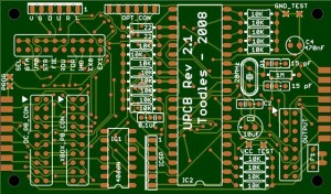
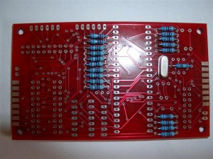
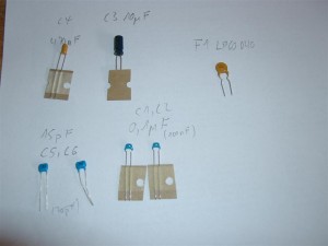
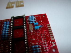
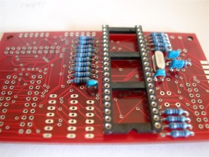
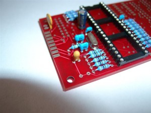
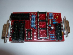
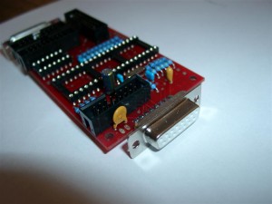
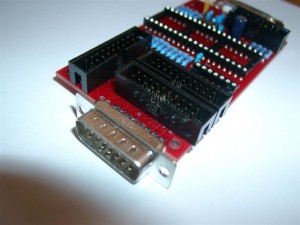
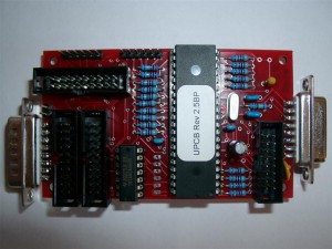
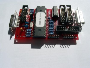
here are some pictures where you can see how to assemble a UPCB Rev 2.1

labelledupcb21qx9

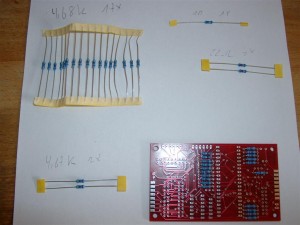
First we have to make the pcb working. Two 4,67k on the botton are not neccasary

upcb_soldering (1)

upcb_soldering (2)

upcb_soldering (3)

upcb_soldering (4)

upcb_soldering (5)

upcb_soldering (6)

upcb_soldering (7)

upcb_soldering (8)

upcb_soldering (9)

upcb_soldering (10)

upcb_soldering (11)

Universal PCB XBox360 Padhack (Piggyback)

Mittwoch, Oktober 14th, 2009

Hi Folks,

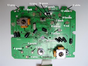
for playing x360 with the universalpcb you will need to hack a x360 Pad.

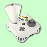
We use a MadCatz Arcade Gamestick Item#4758.

picture of arcade gamestick

picture of arcade gamestick

It will be easy to hack, because you will need no inverting the R-Trigger and L-Trigger Buttons, it’s cheap, you can solder directly to the buttons and it’s common Ground.

We have some in stock: here

You have to dissassemble the complete pad including the R-Trigger and L-Trigger Potis.

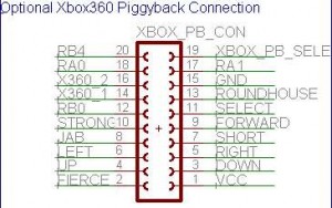
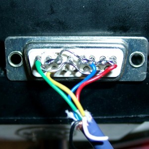
Connector on UPCB
Connector on UPCB

Pin Color
1 black VCC Red usb cable
2 white 7 Hard Punch FIE=FIERCE RButton
3 grey DOWN DOWN
4 purple UP UP
5 blue RIGHT RIGHT
6 green LEFT LEFT
7 yellow 1 SHO=SHORT Light Kick A (green)
8 orange 5 JAB Light Punch X (blue)
9 red 2 FOR=FORWARD Medium Kick B (red)
10 braun 6 STR=STRONG Medium Punch Y (yellow)
11 black L-PB SEL=SELECT Back
12 white R-PB RB0 Start Start
13 grey 3 ROU=ROUNDHOUSE Strong Kick LButton
14 purple
XBOX360_1 D- (white)
White usb cable
15 blue Gnd Black usb cable
16 green
XBOX360_2 D+ (green)
Green usb cable
17 yellow 4 RA1 LT „hardest“ Kick LTrigger
18 orange 8 RA0 LB „hardest“ Punch RTrigger
19 red XBOX PB Select (high when in use)
20 braun RB4 Guide (press LeftPinballB+RightPinballB) Guide
Frontside of the MadCatz Pad

Frontside of the MadCatz Pad

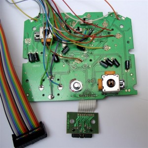
frontside including Wires

frontside including Wires

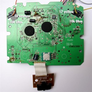
Backsite including Resistors 10k

Backsite including Resistors 10k

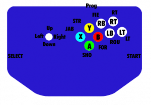
ButtonLayout

RGB-Led for Sanwa JLF-TP-8YT Stick

Dienstag, Oktober 6th, 2009

Hi there,

for having fun with the great Sanwa Sticks I want to use a transparent Balltop and a Stick with a hole.

Thanks to luigi for the necessary hardware.

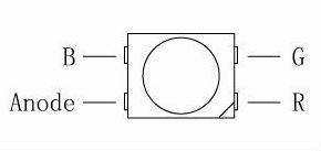
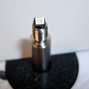
If you want to make it lid RGB you are in need of some SMD Led´s. First I tried SMD 605 (small Leds) but now I will try the bigger one called PLCC-2 DMX RGB-Leds.

pinout plcc2-rgb

pinout plcc2-rgb

IF=20mA, Red=2,0V; green=3,5V; blue=3,6V

-> Rred=150Ohm; Rgreen=125Ohm; Rblue=120Ohm @ 5V

You need 4 wires and shrinking tube.

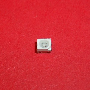
plcc2-dmx

plcc2-dmx

(in real)

heatshrink tube

heatshrink tube

(shrinking tube 2 sizes)

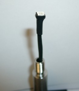
final position of rgb-led

final position of rgb-led

electronic attachment

Montag, Oktober 5th, 2009

The complete electronic was attached to the PVC Cover.

Now I have to attach it to the Panel itself.

too be continued…

Opening the LCD

Montag, Oktober 5th, 2009

To get an authentik look I am using original Pinball Stuff for the PINbrawl like PinballLegs, Lockbar.

The first Problem was the wide of the Pinball. I want to use a WideBody Lockbar. To see if the LCD fits, we must open it to have look of the native Wide of the LCD.

Toshiba Backsite Open

Toshiba Backsite Open

You can See the PC of the LCD at the bottom of the picture and in the middle the powersupply

PVC Removing

PVC Removing

First I have to remove two little pcb’s (Status Leds, IR-Receiver) and the speakers.

After this I removed the complete PVC Cover. The native LCD wide is: 57,5cm.

A widebody Pinball is 62,5cm

I want to use 19mm MDF for the Cabinet so I am lucky it will work.