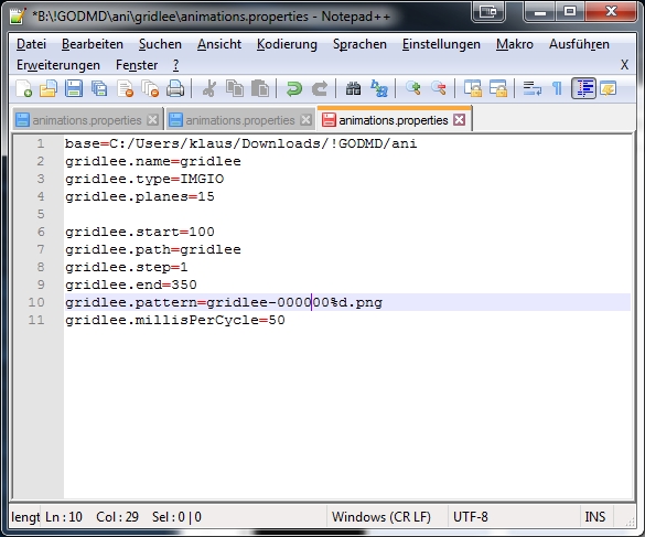
Here you will find a package including one demofile. gridlee You only have to change variable base to your path were the package extracted
To do some animations for goDMD you have to use mame. I am using groovymame, because it can be set to output native pixel resolution of the games. So you will get a pixelperfect output for the goDMD.
start mame via commandline: groovymame -mngwrite griddle.mng griddle and do some gaming. After exit you will find a griddle.mng.
To split the griddle.mng into pictures I used a programm advmng
start it in the path where the griddle.mng via commandline: advmng.exe -x griddle.mng
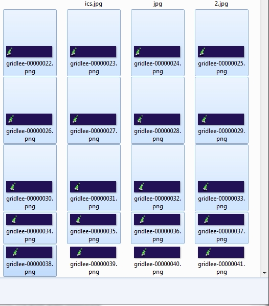
After this you will get a lot of pictures like: gridlee-00000022.png (Resolution: 245×240)
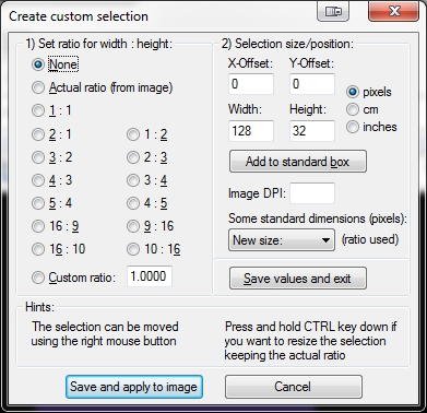
With the help of irfanview (a pictureviewer) you can create a custom selection (under edit) with Width: 128 and Height: 32.
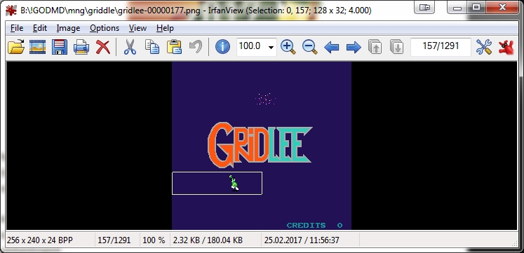
After Pressing the Button: Save and apply to image you will see a window on top of the left png.
Move it with the help of arrowkeys to the area of interest
In Top Line you see (Selection: 0,0) this marks the X,Y Position. You have to enter these values in
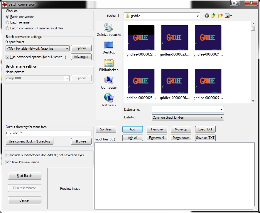
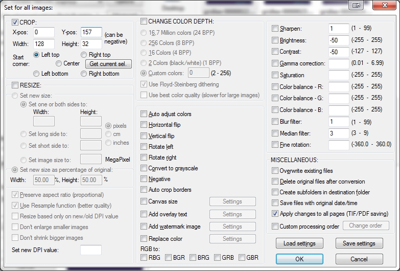
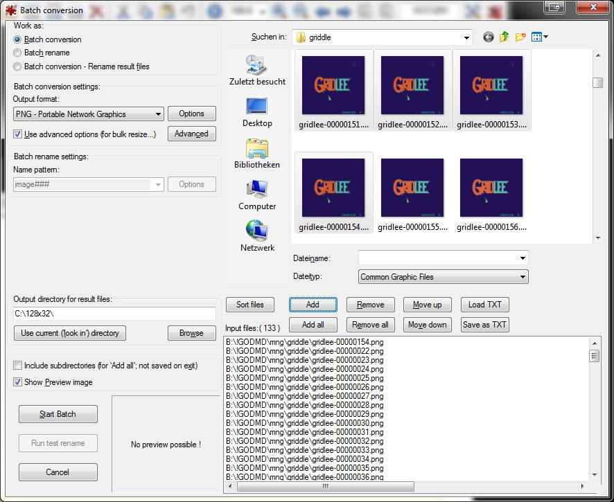
Under File: Batch conversion (set to PNG Output Format) and press Advanced Button: Here you can set the X-pos, Y-pos Position
Mark the amount of png you want to crop and add them
Start Batch
now you have a lot of cutted pictures in the right resolution
now put a animaions.properties in this folder
After this try to import it in the pin2dmd editor under animations: Load Animations
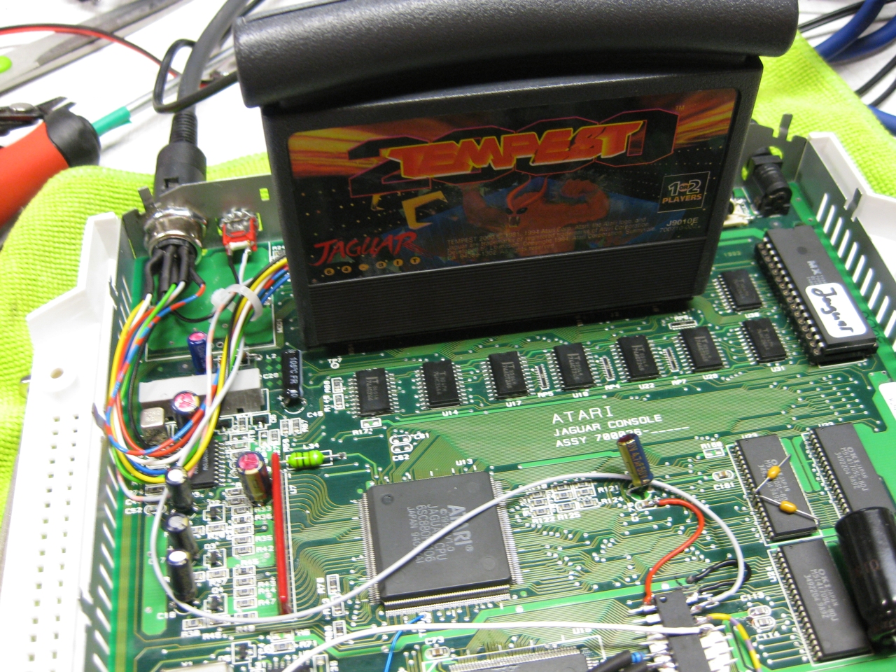
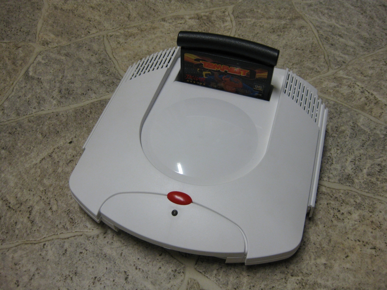
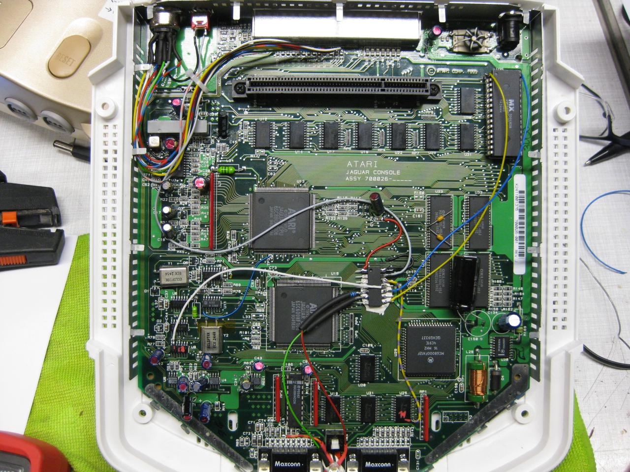
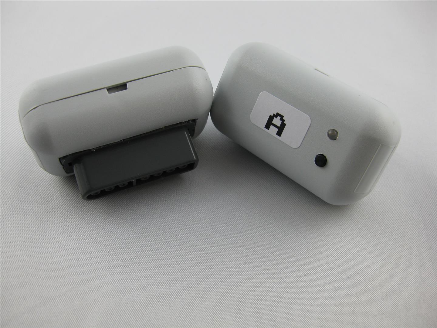
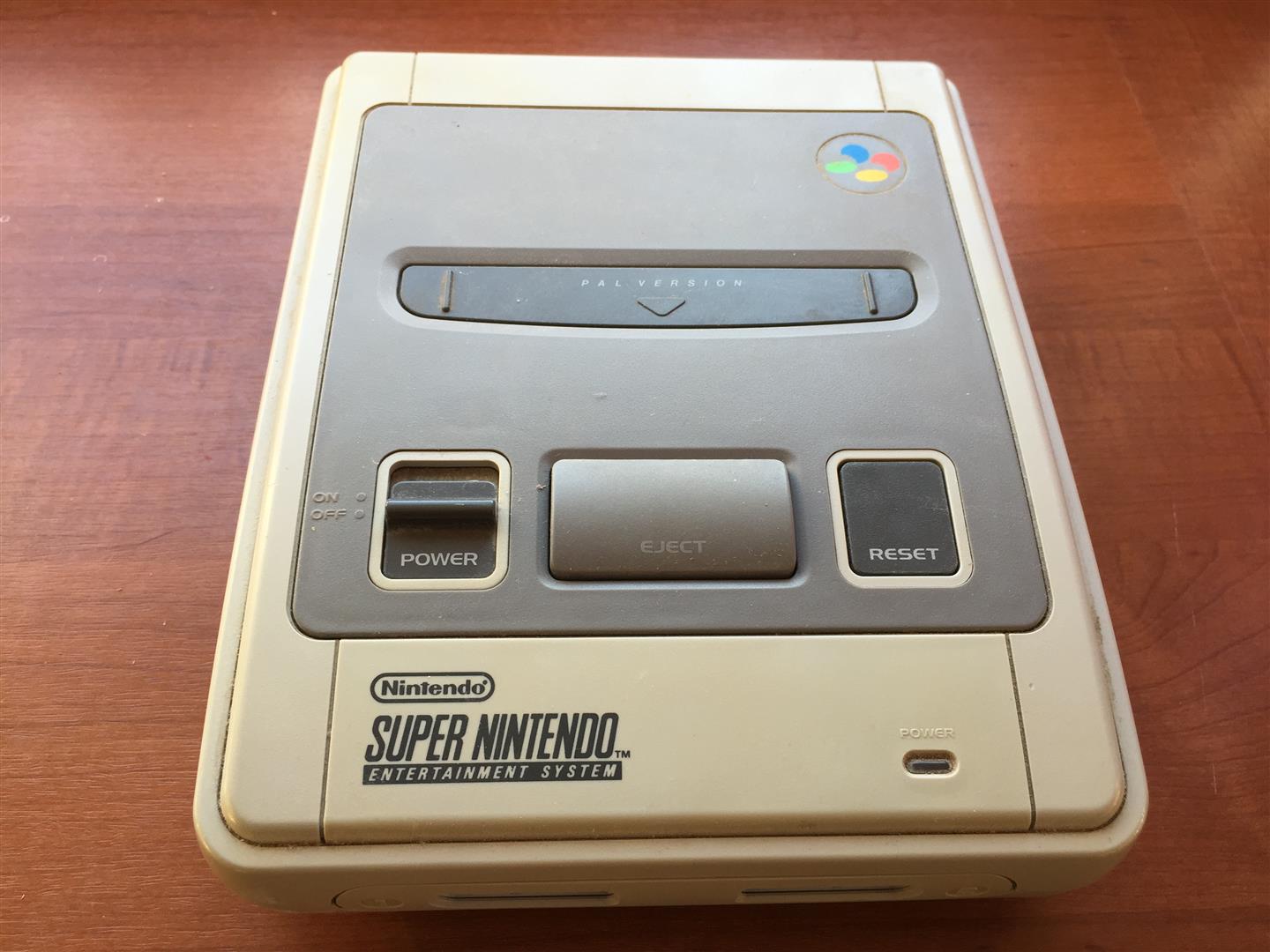
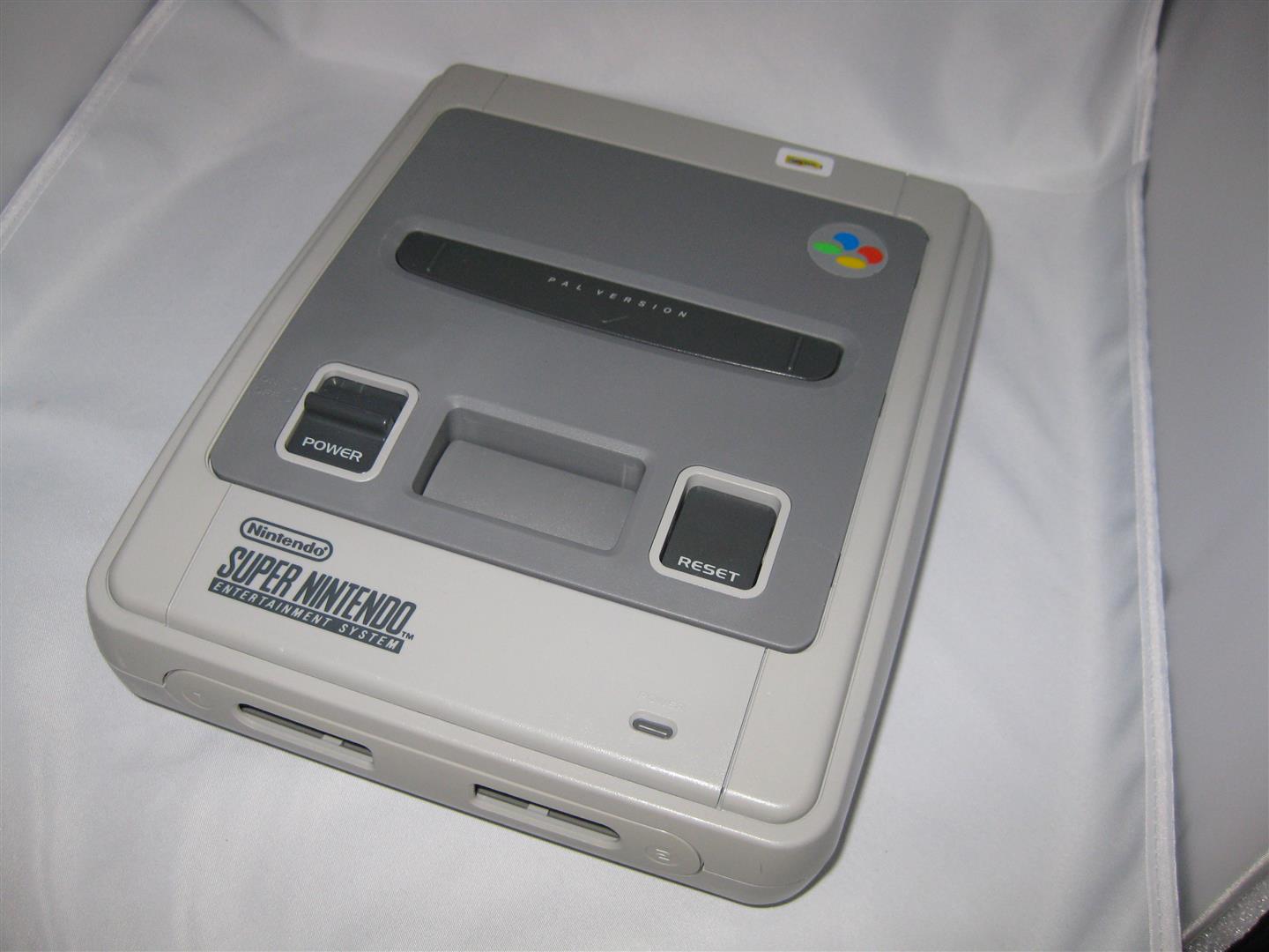
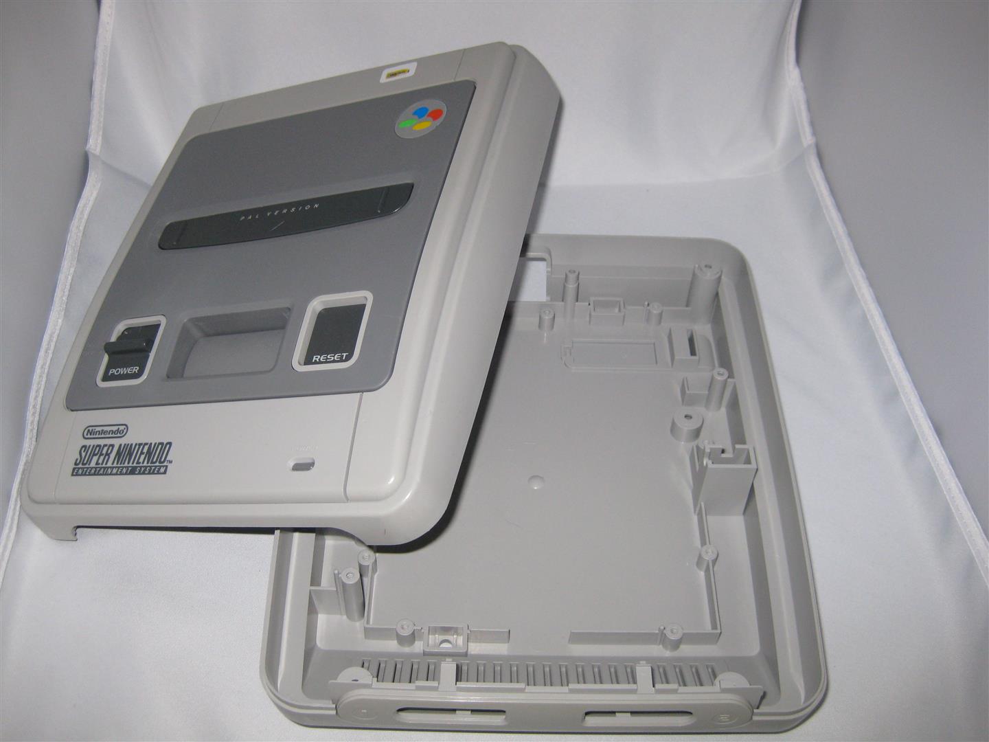
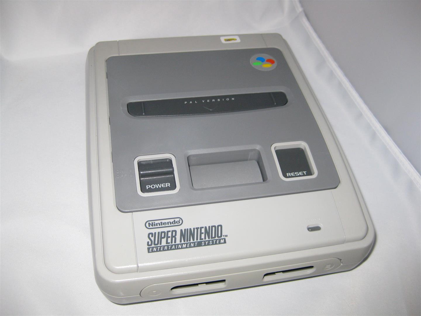
I got a white „dental“ case and its time to make the jaguar ready for 2017
The title is something strange, but its comming from a Sega Saturn Mod years ago (the code is based on this). The Saturn reset button is used for change region and 50/60Hz.
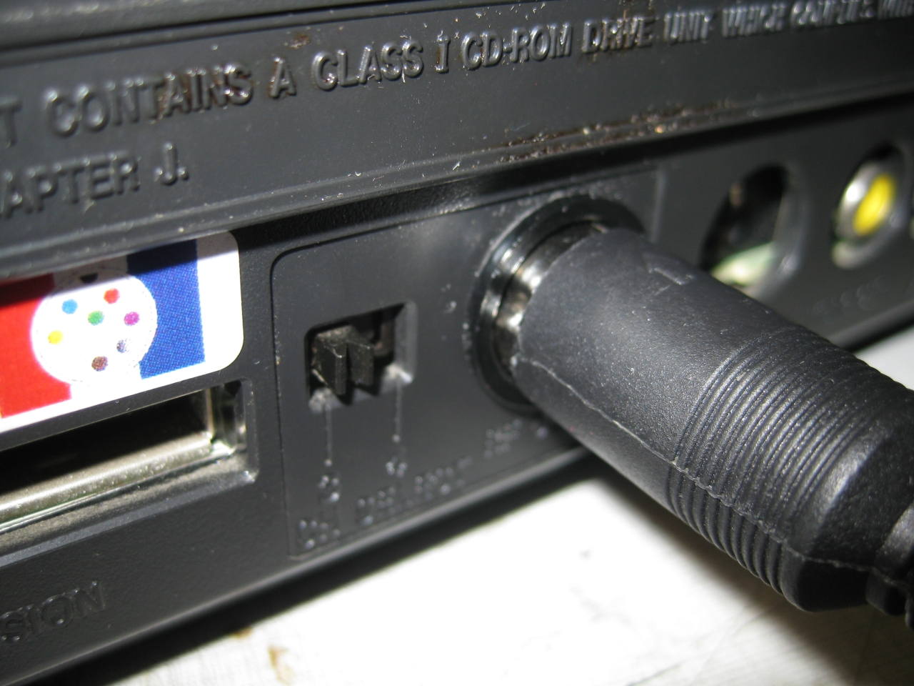
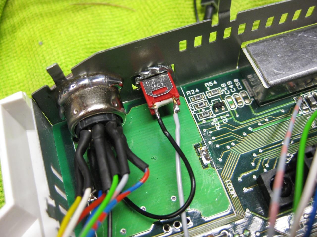
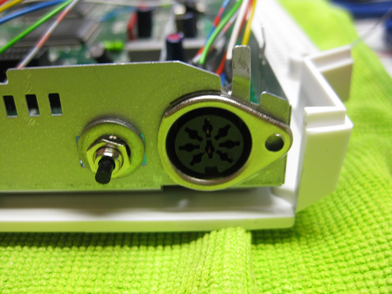
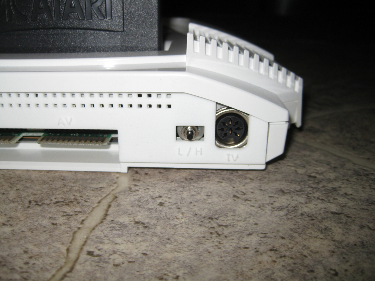
I removed the RF-Unit to put my „standard“ DIN Connector and for adding a button instead of the chanel selector. With the help of this tiny button you can select between 50/60Hz.
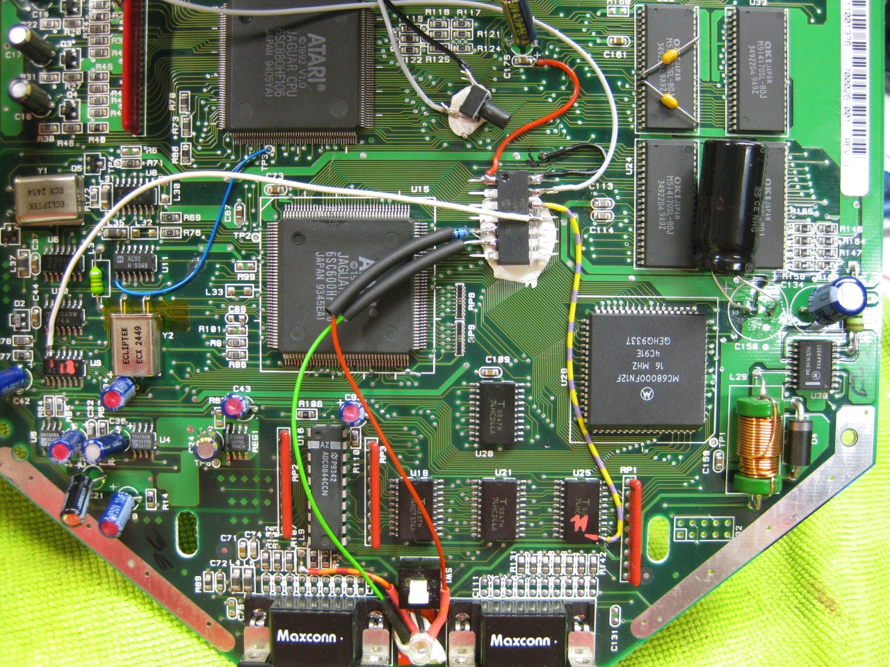
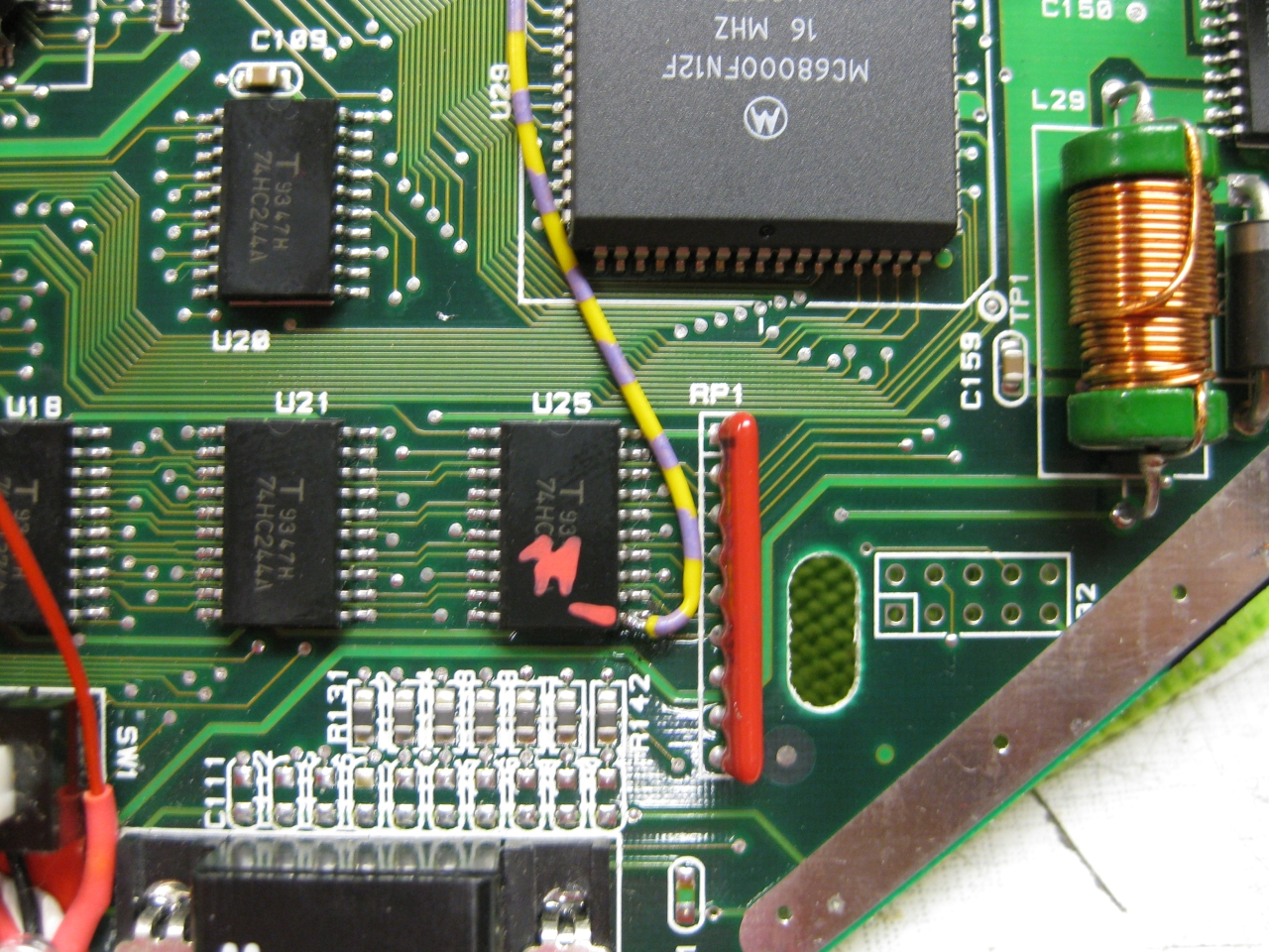
(Overview)
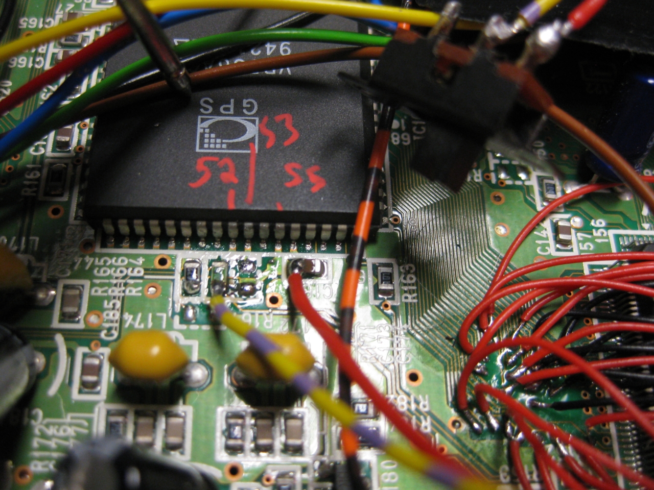
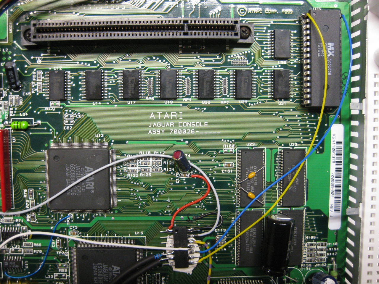
(U25 Pin 11 sets the Console between 50 Hz (GND) and 60Hz (5V)
I used a US 60Hz Jaguar for modding, so you have only to solder this wire to Pin 11
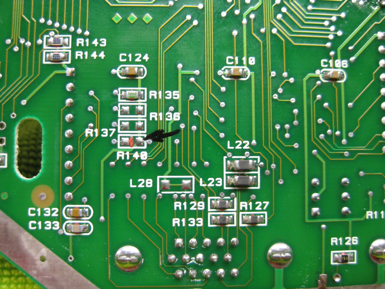
Attention If you use the PAL console you have to look downunder and remove a Resistor R140!
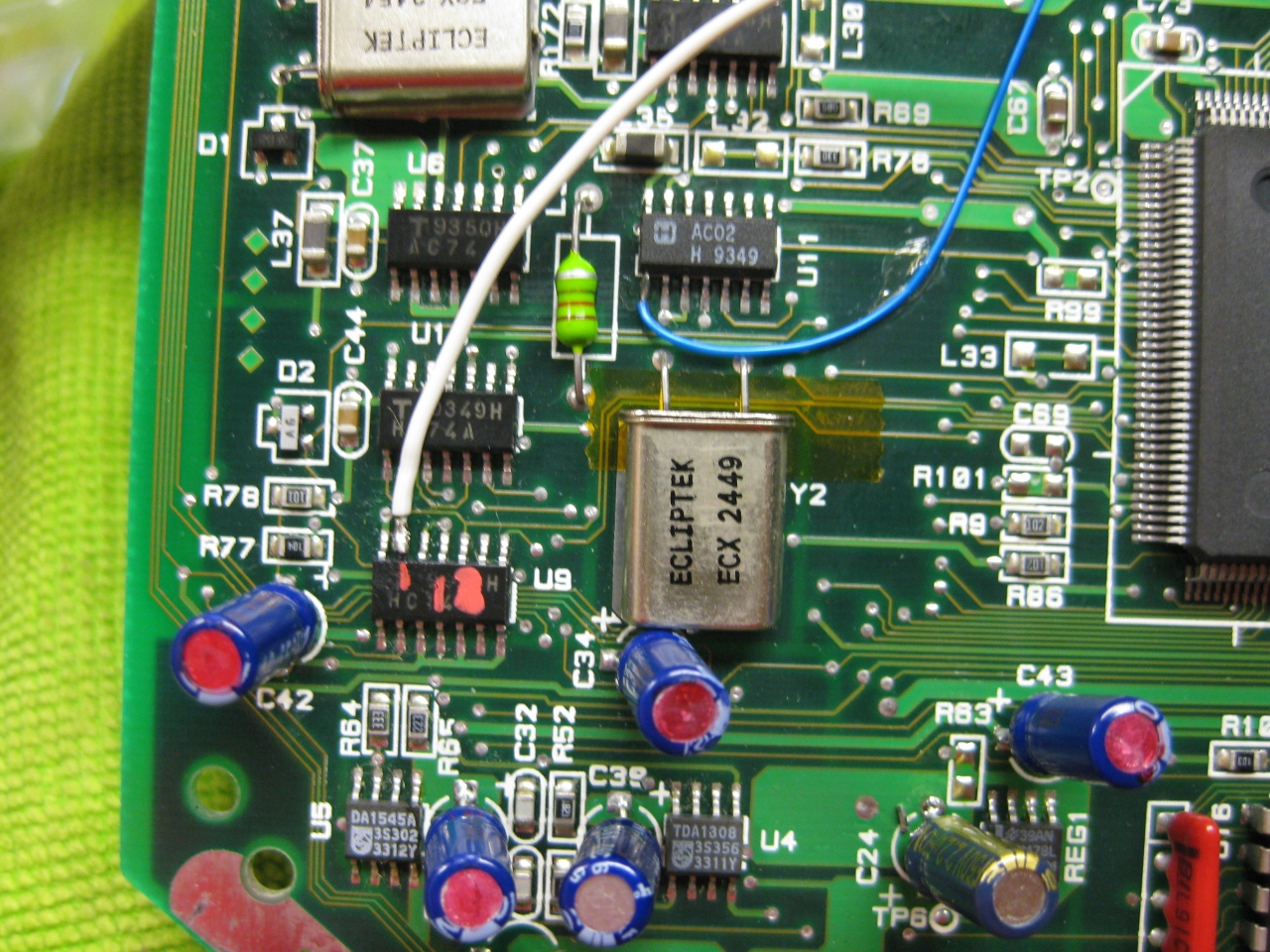
(The Reset Line you will find U9 Pin 13 (GND = reset)
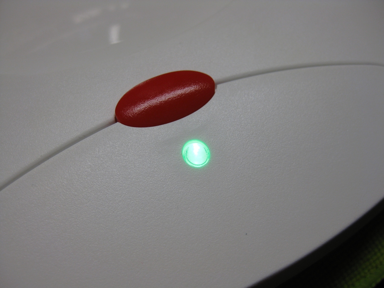
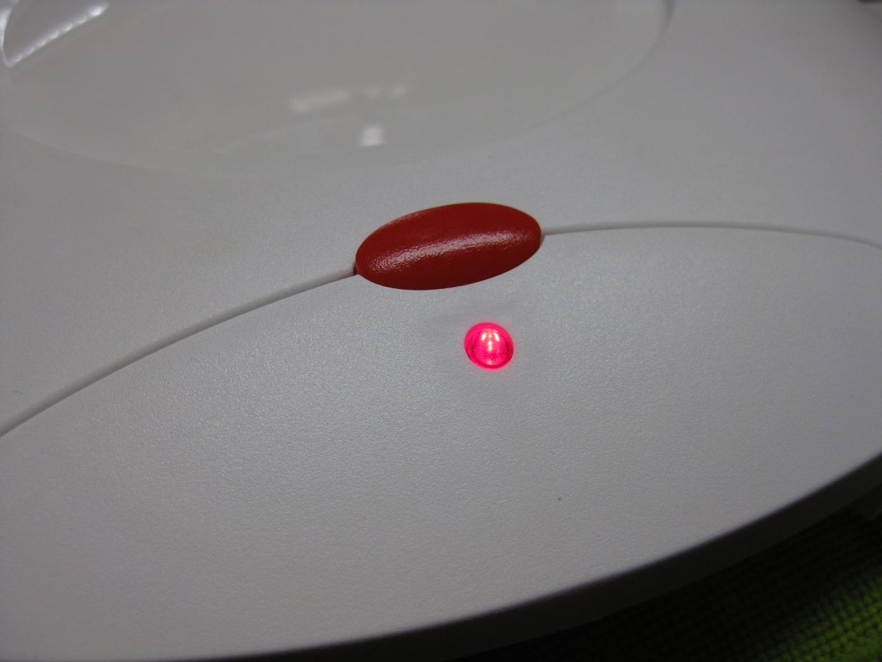
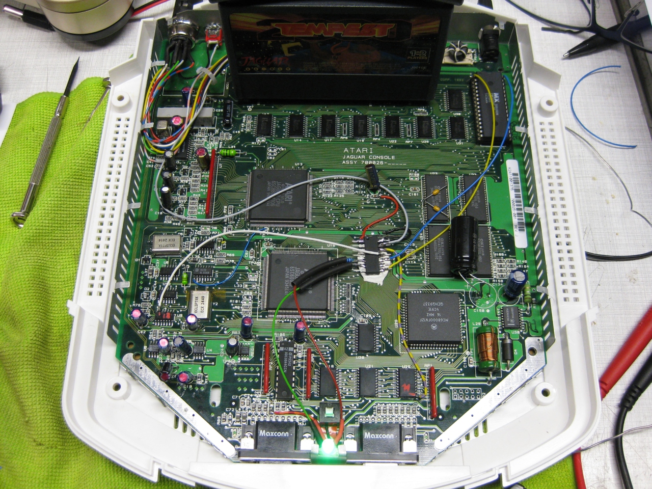
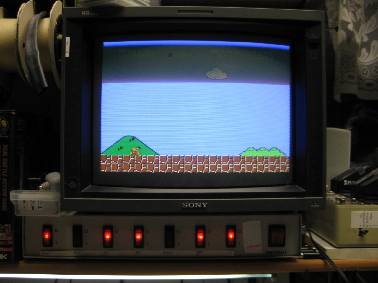
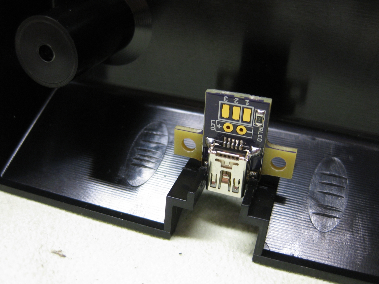
I removed the original LED and put instead a RGB-Led.
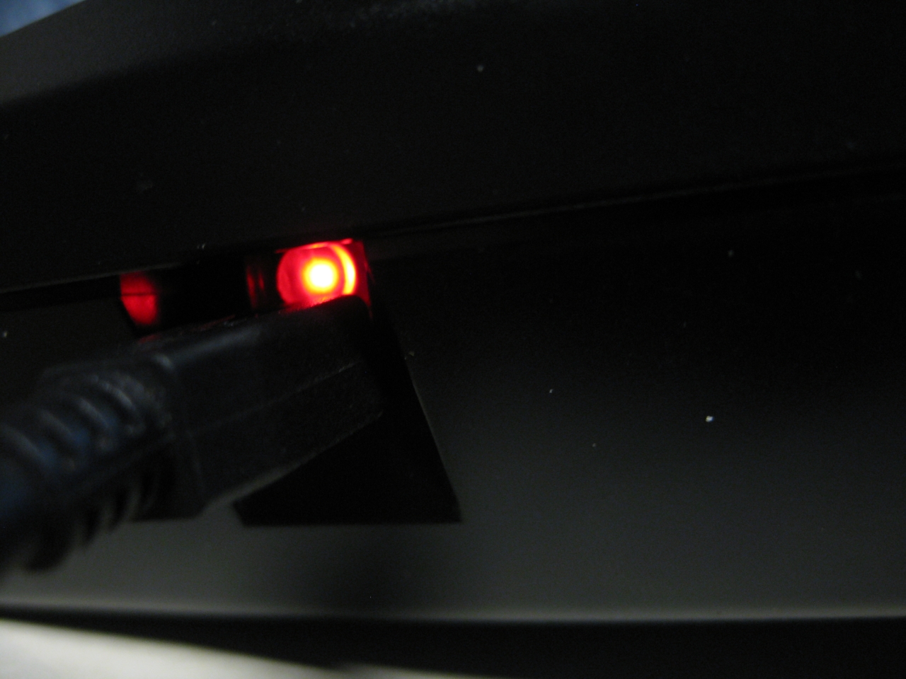
I set red for 60Hz and green for 50Hz.
If you find blue better, no problemo. But red/gn are the real colors of the Jaguar used in their countrys.
Usage:
Its like the switchless Mod for the Sega Saturn.
a) When you push the button for a moment. The Jaguar will do a reset
b) you push and hold the button. Now the Color of the LED will toogle between green and red. When you release the button
at red -> Jaguar Resets and starts with 60Hz
at green -> Jaguar Resets and starts with 50Hz
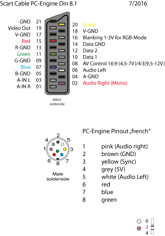
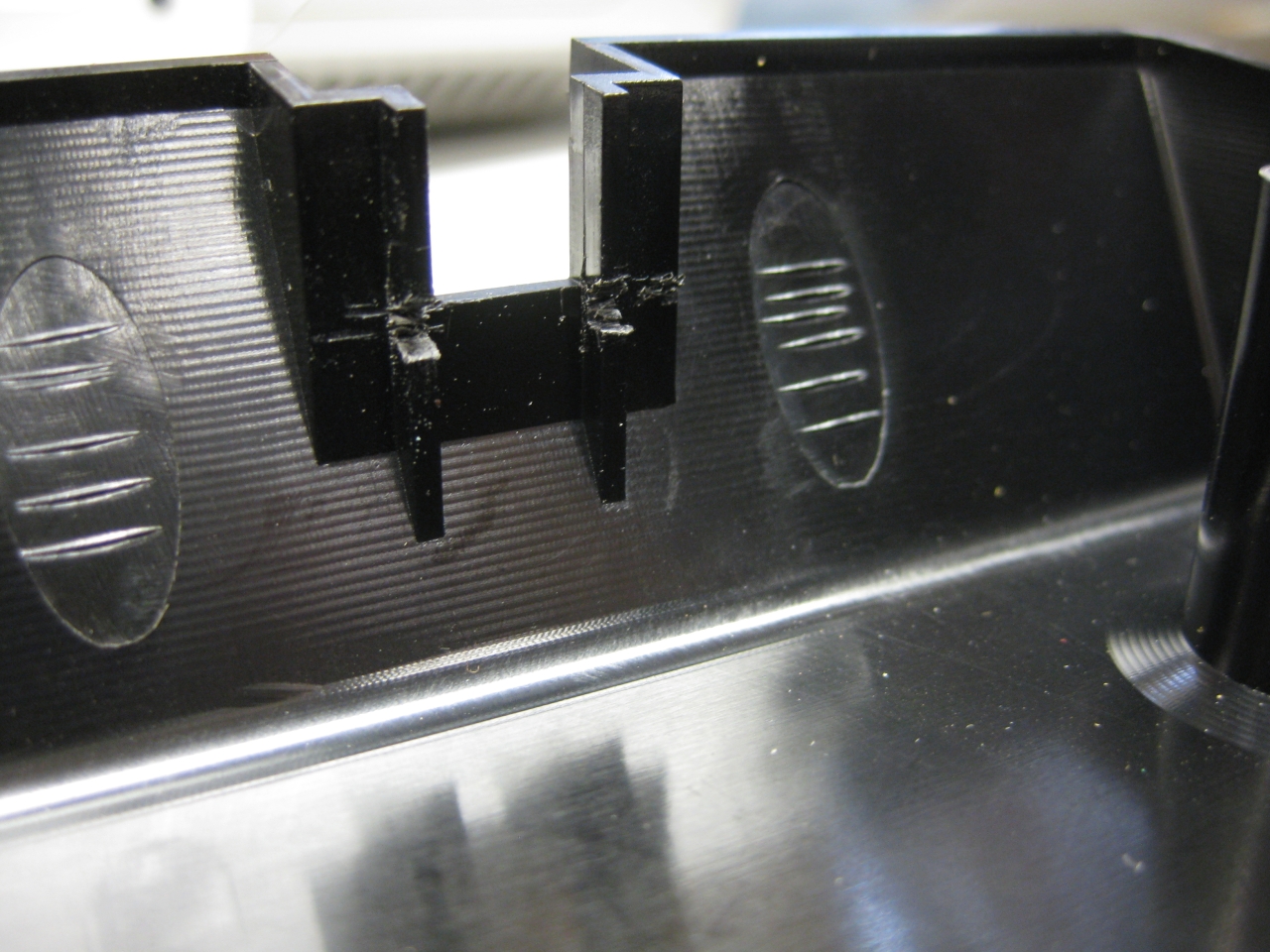
(bigger hole for Din RGB-Connector)
(RGB-Pinout)
(Reset button)
(overview)
(my standard Din Pinout, based on modified 5 Pin Din PC-Engine + 3 more for RGB)
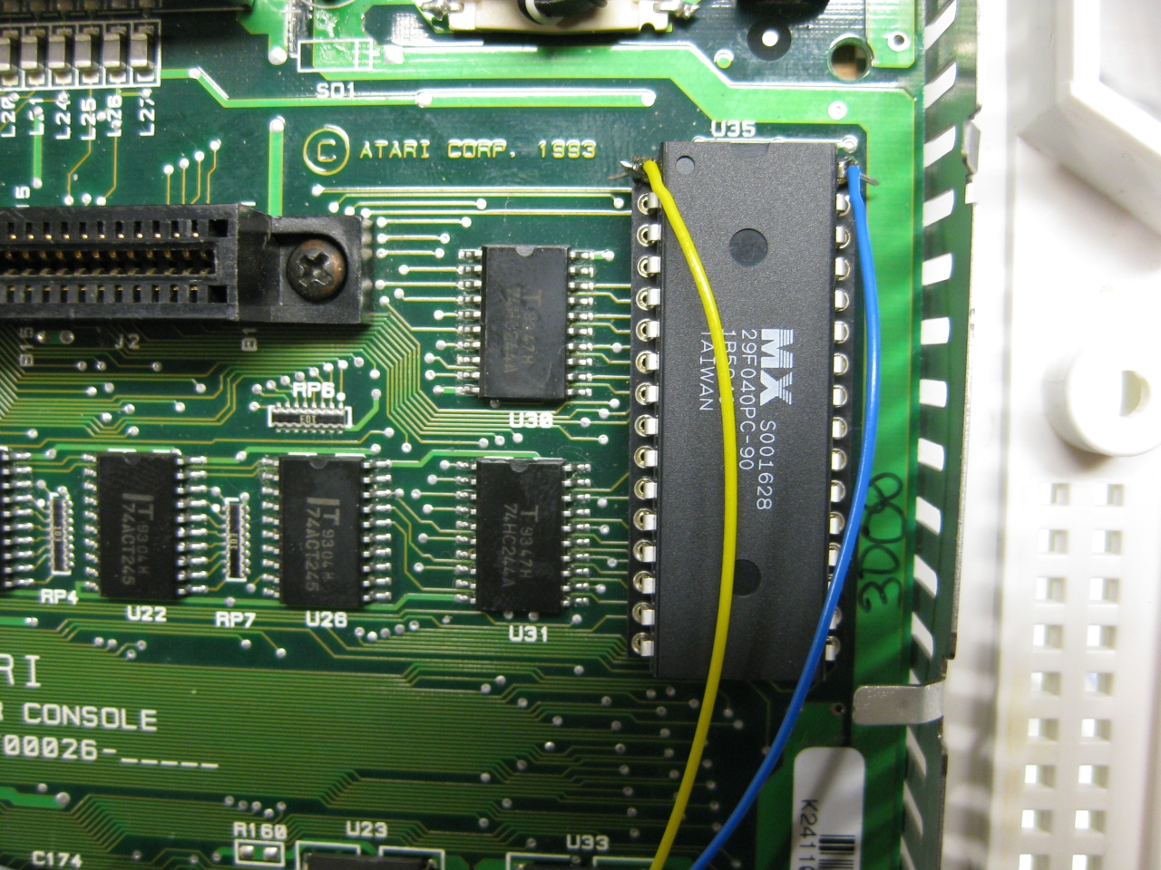
Its time to add a 2nd Bios to the Jaguar.
You have to remove the original Jaguar Bios and use a DIP 32 socket.
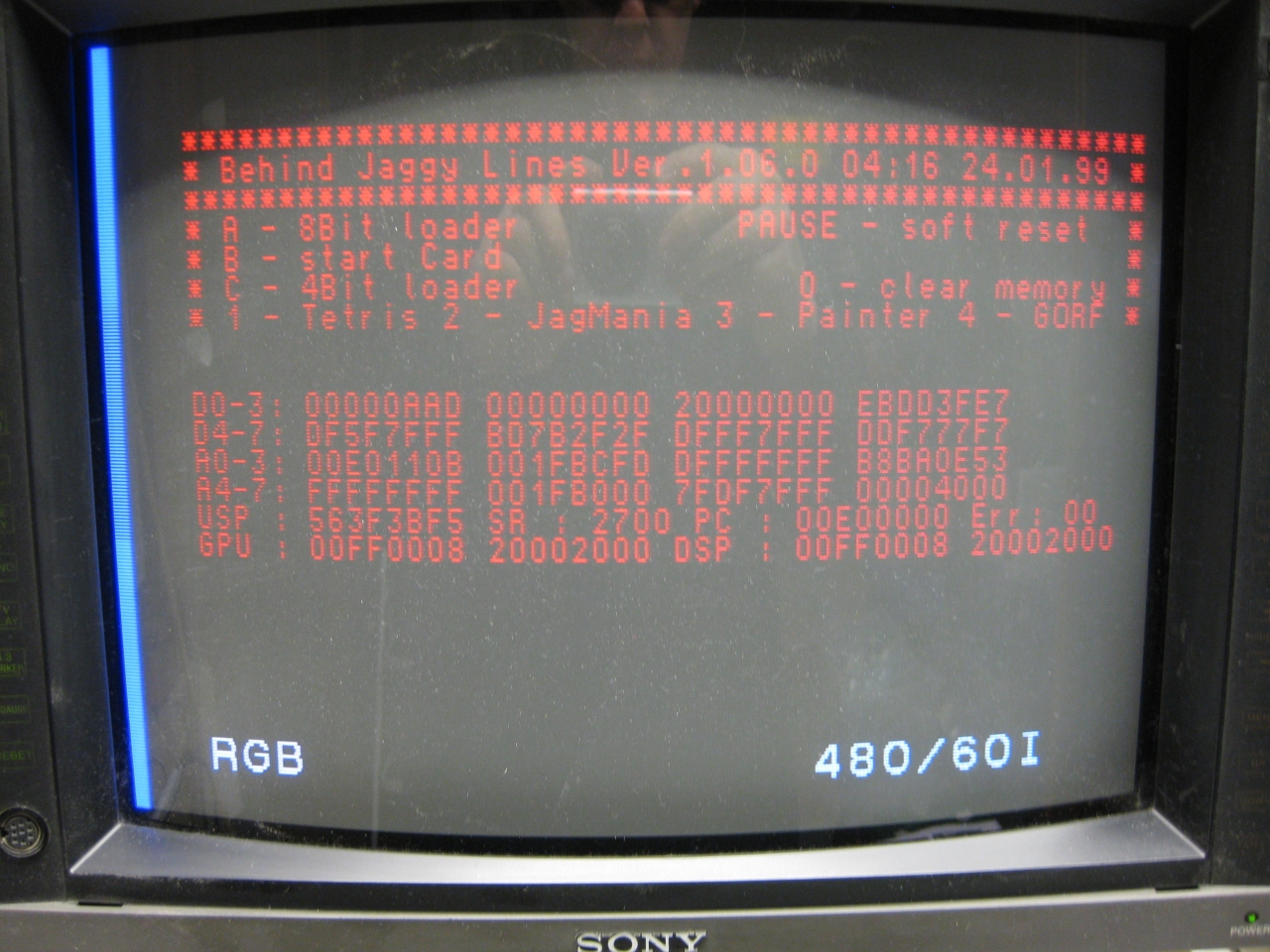
With the help of a 29f040 FlashRom I added jagbios and BJL1.06
You need to concat the bios files:
Use: windows command: copy /B jagbios.bin + jagbios.bin + jagbios.bin + BJL106.bin 4in1bios.bin
and burn 4in1bios.bin to the 29F040 FlashRom
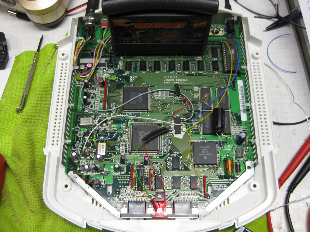
(overview)
Update 23.6.2017
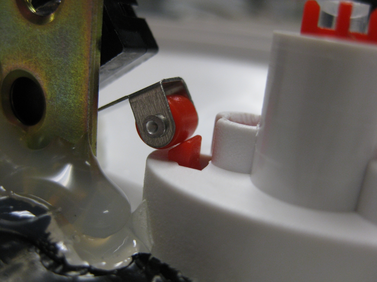
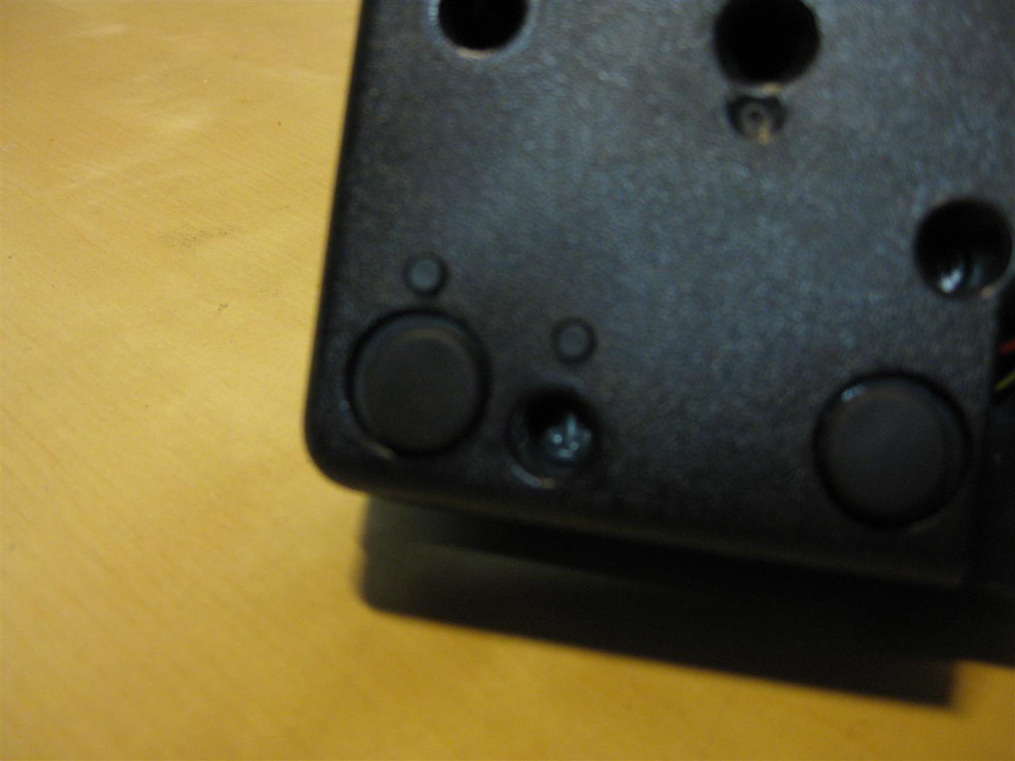
I put a switch beneath the Power Switch to make it like a „real switchless“ mod.
So the Power switch can pressed a litte to:
change 50/60
Reset
switch between original Bios and BJL
OR
Press it more deep to Power Off and Power ON like normal
I used a little switch with a ball at the end and put it inside like this:
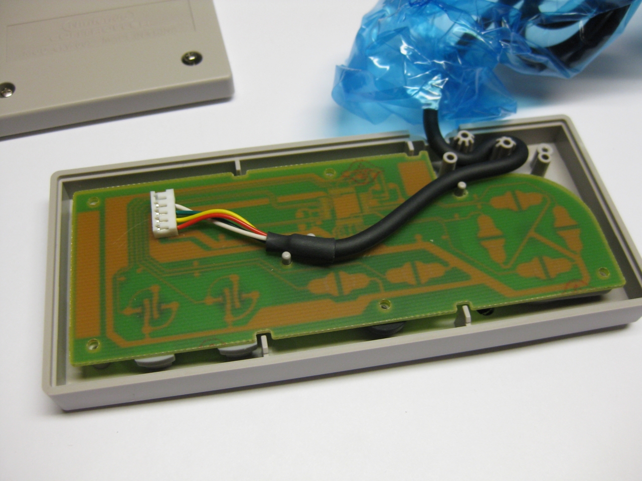
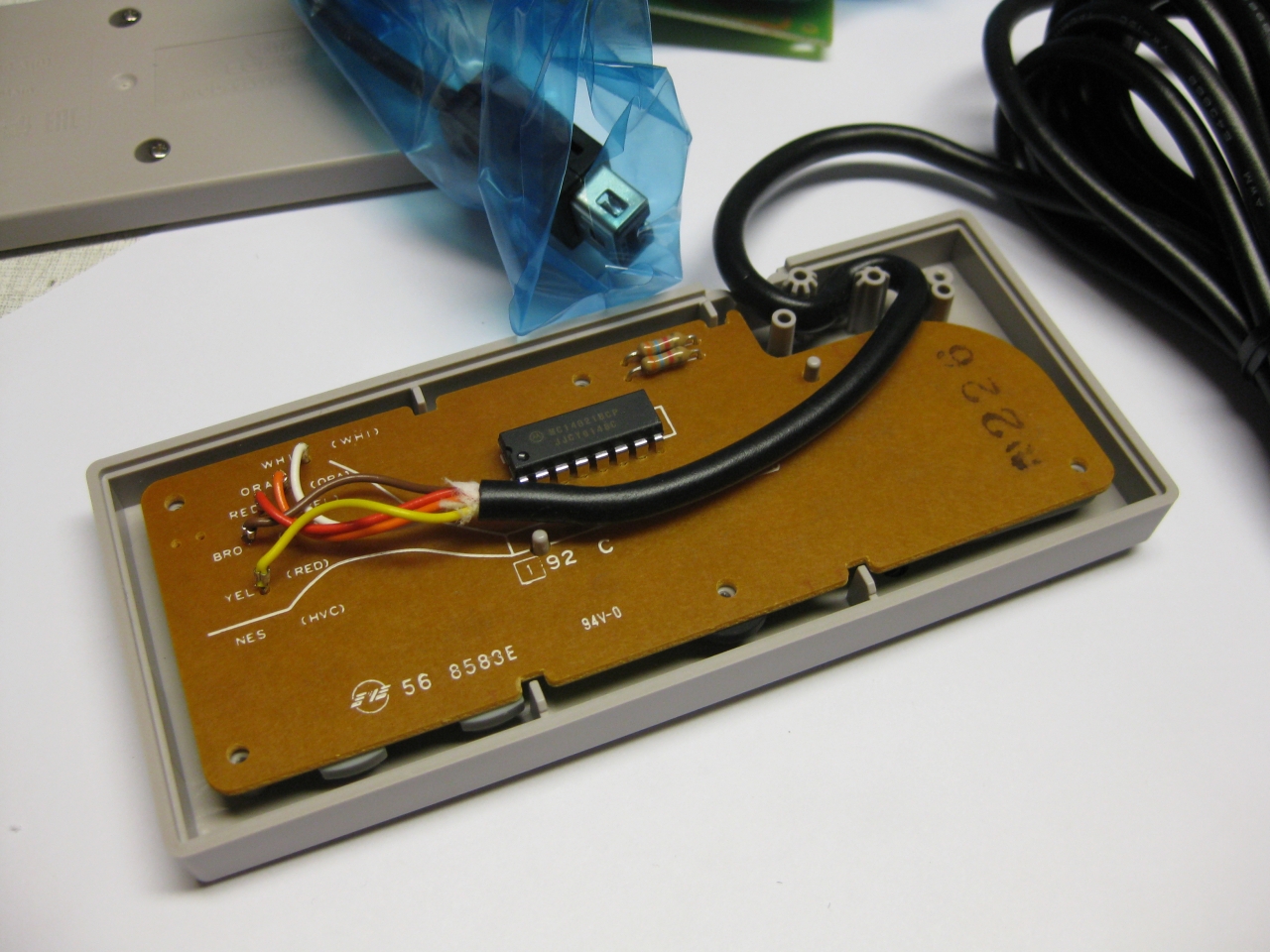
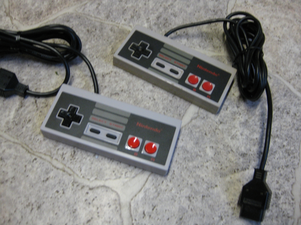
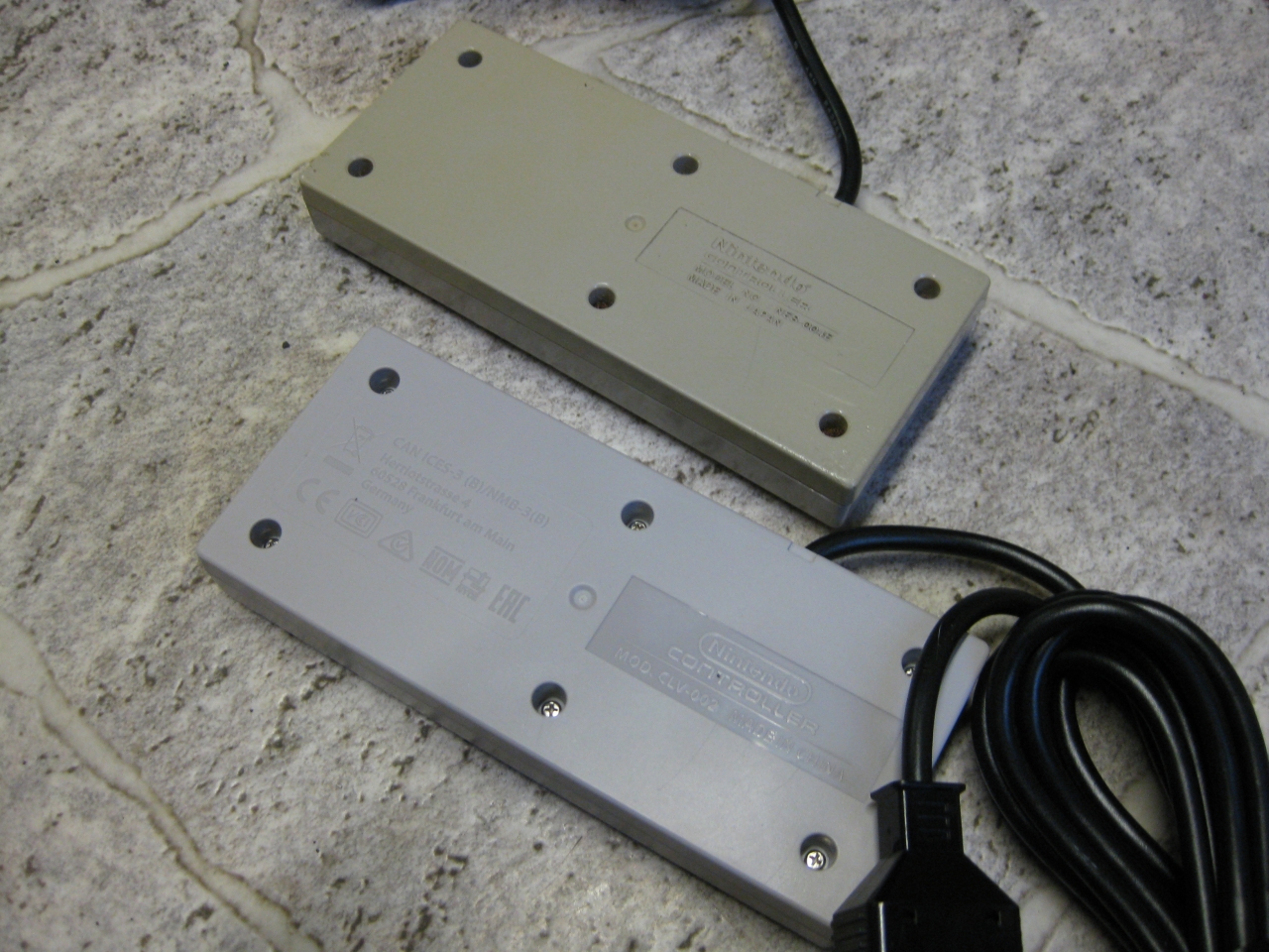
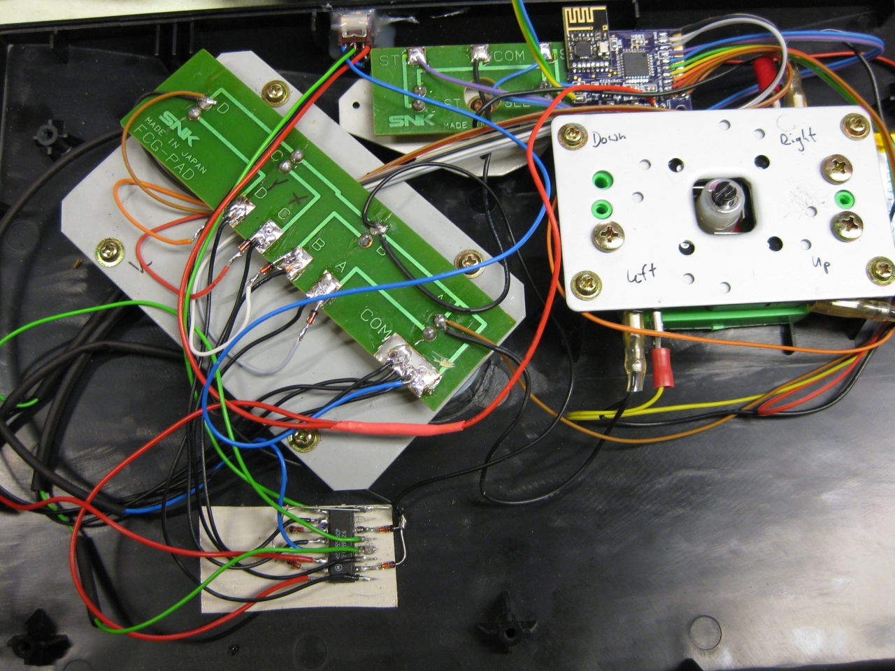
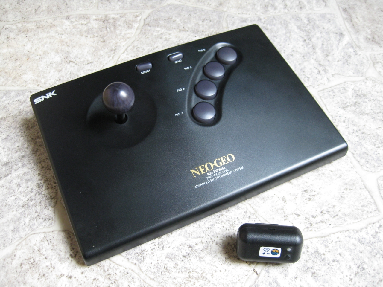
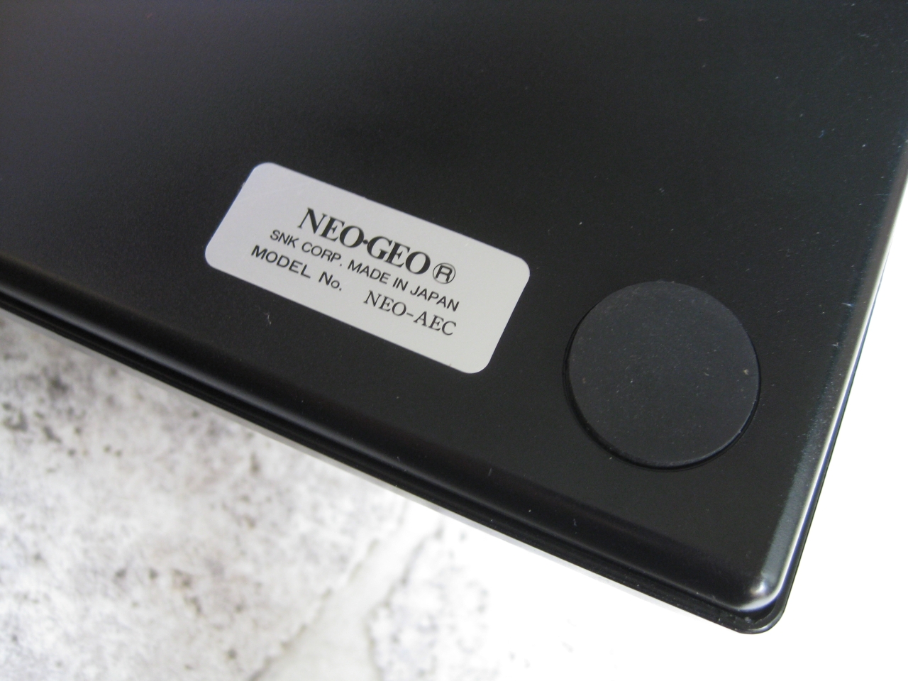
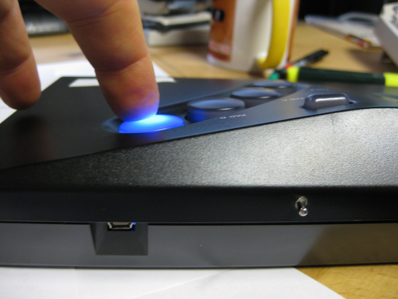
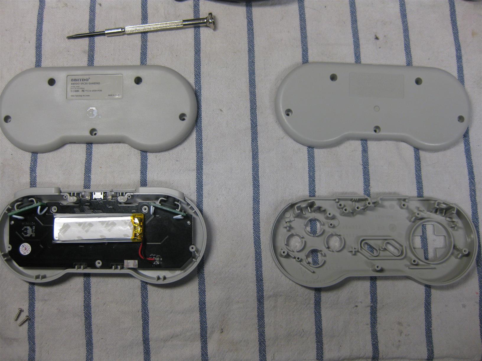
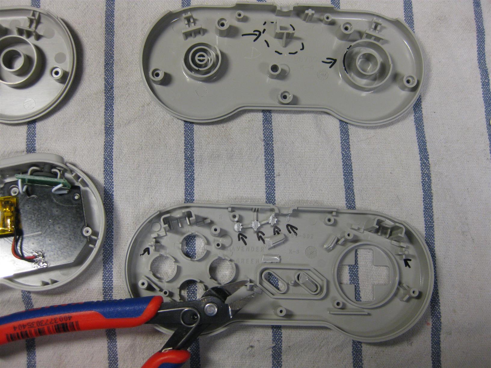
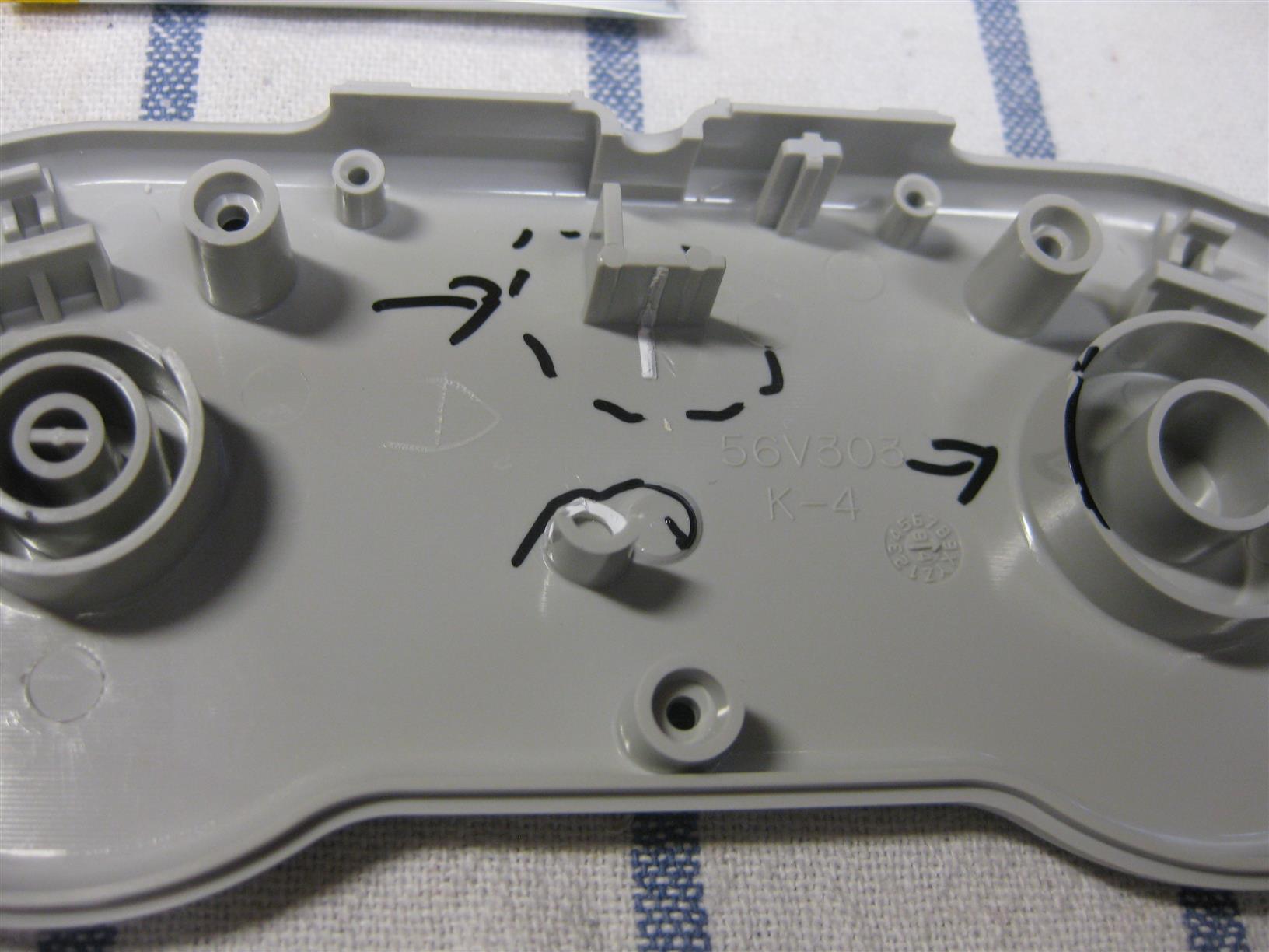
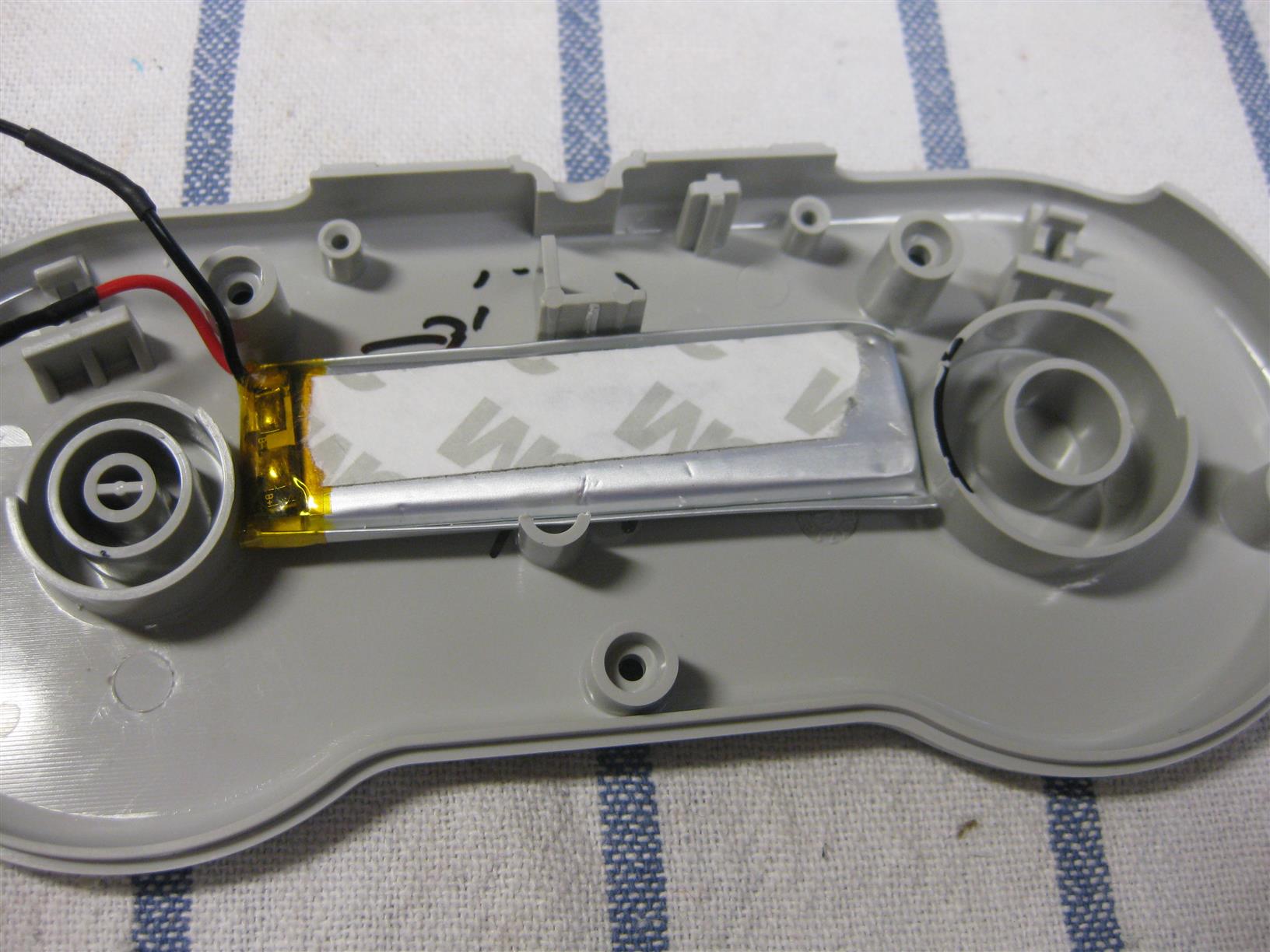
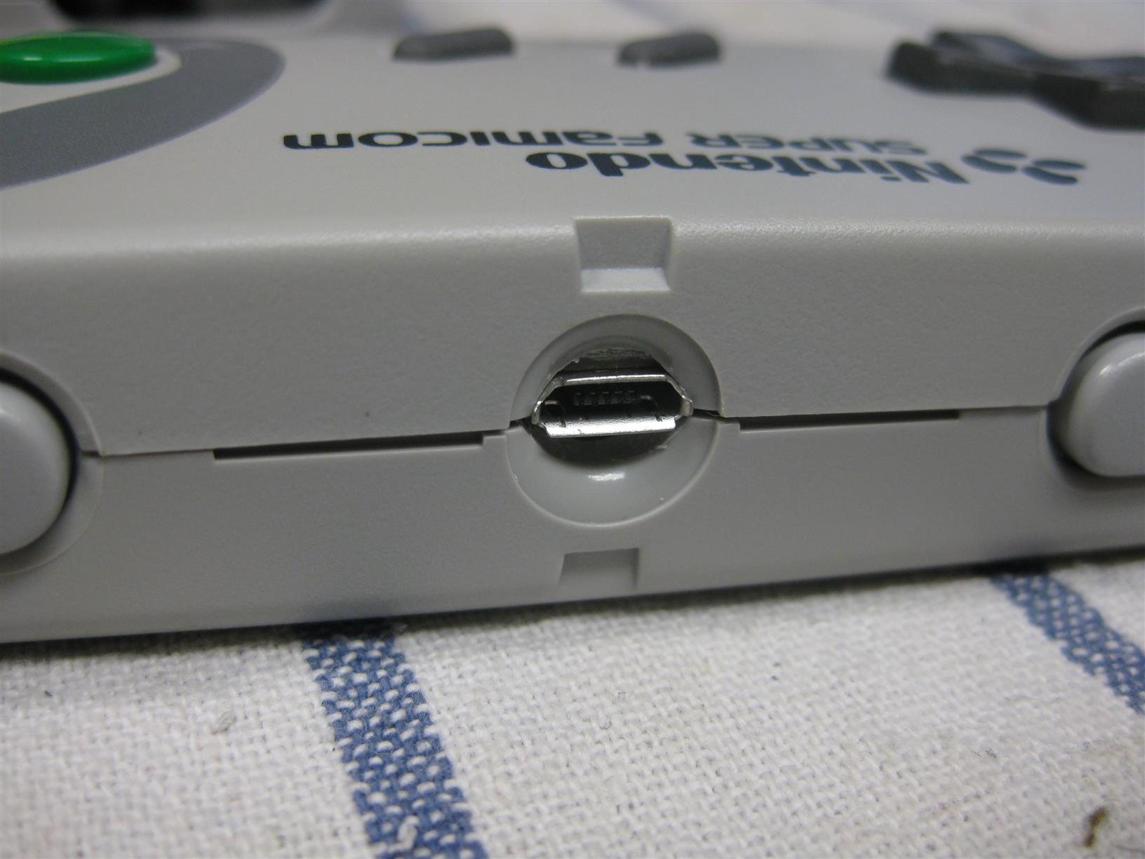
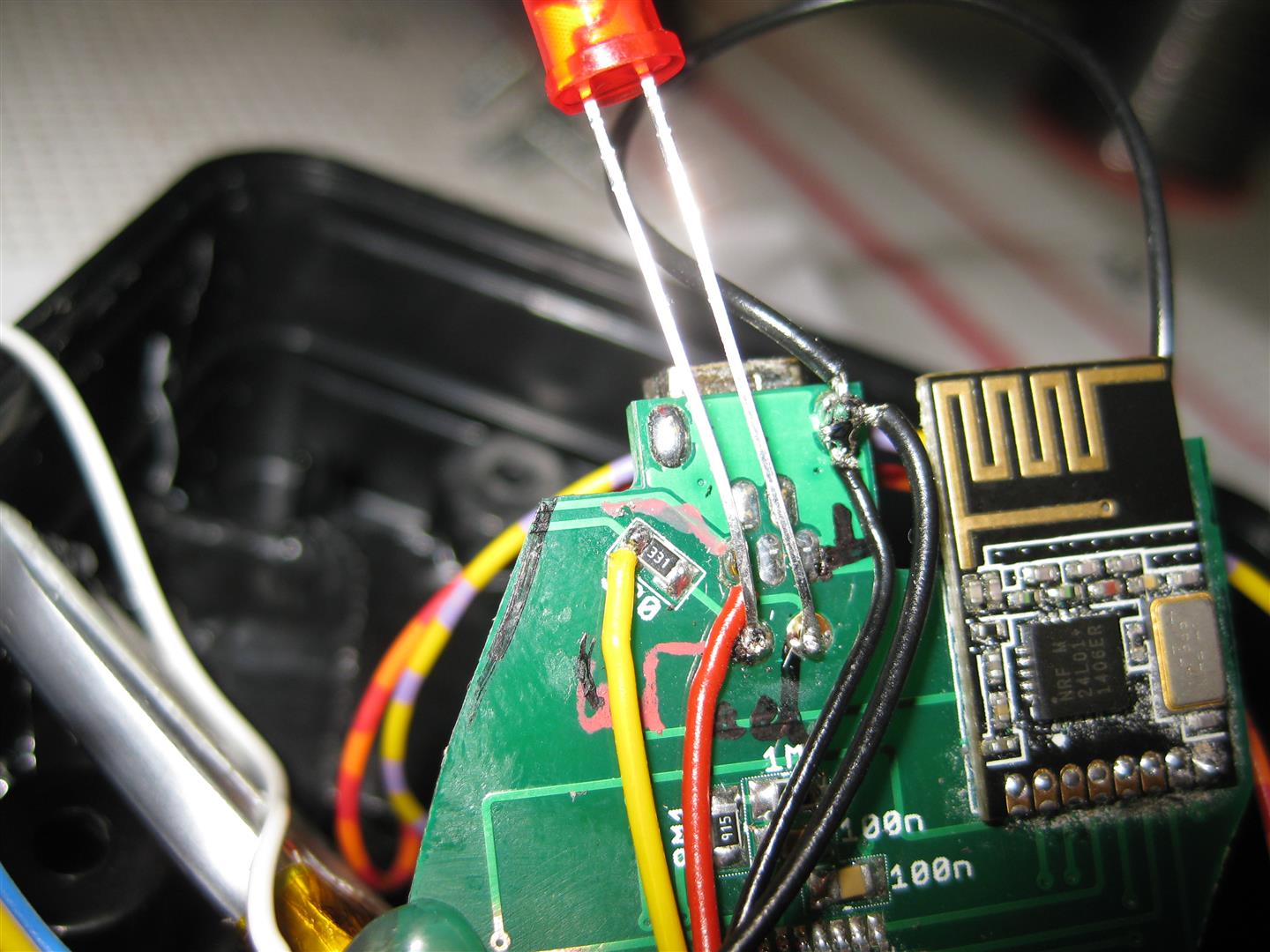
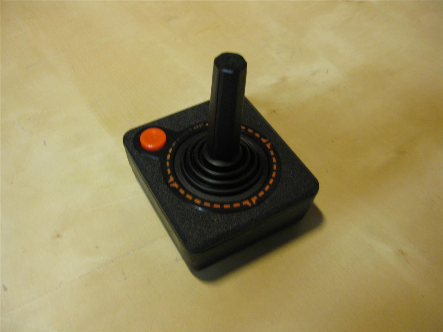
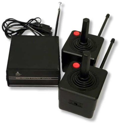
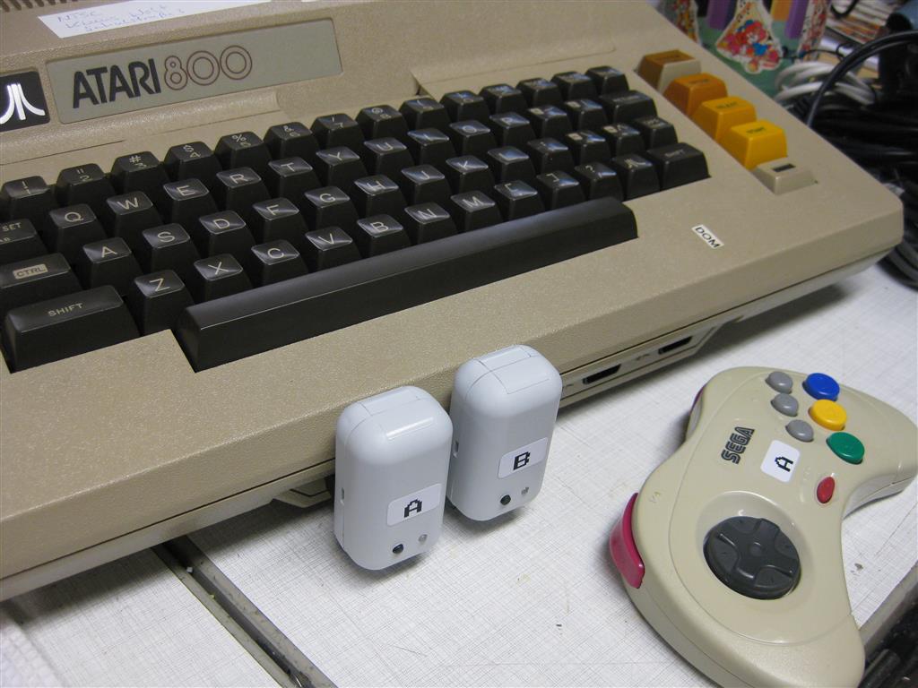
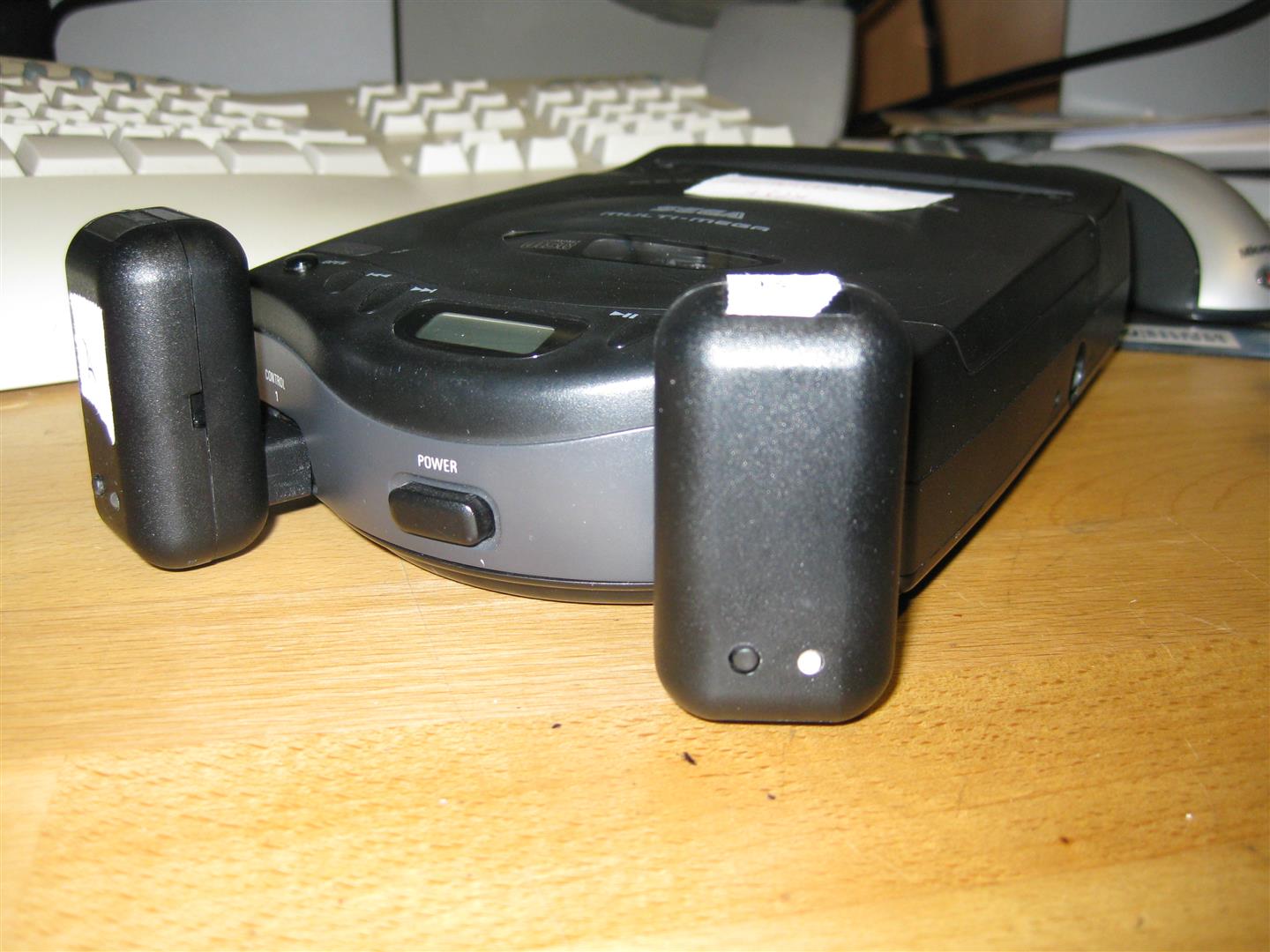
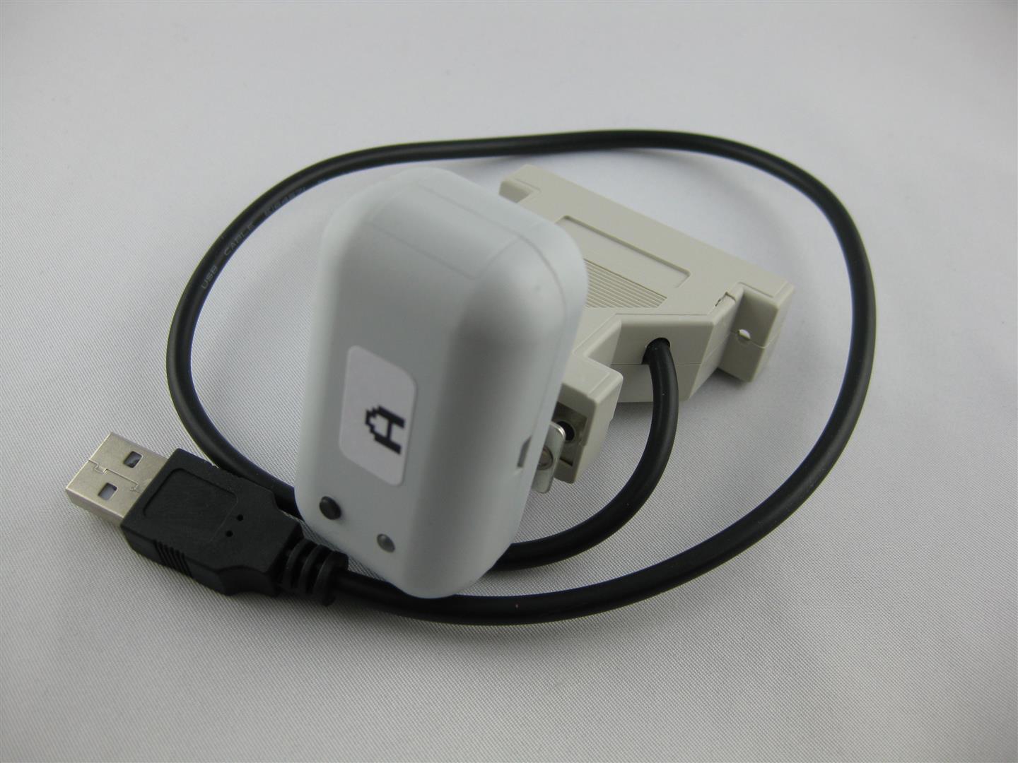
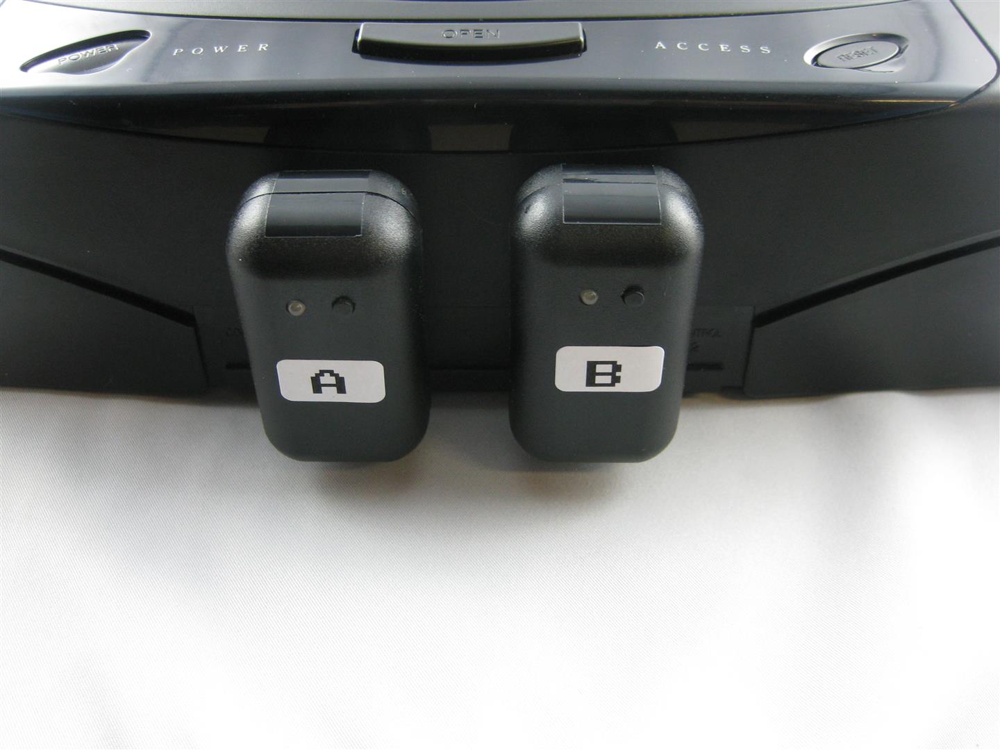
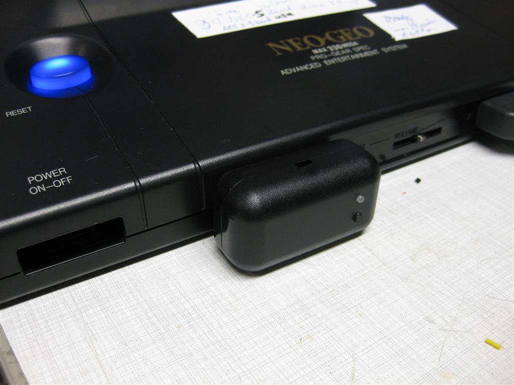
I sacrifice my NeoGeo Board to make it wireless with uwrc. thanks to micro again.
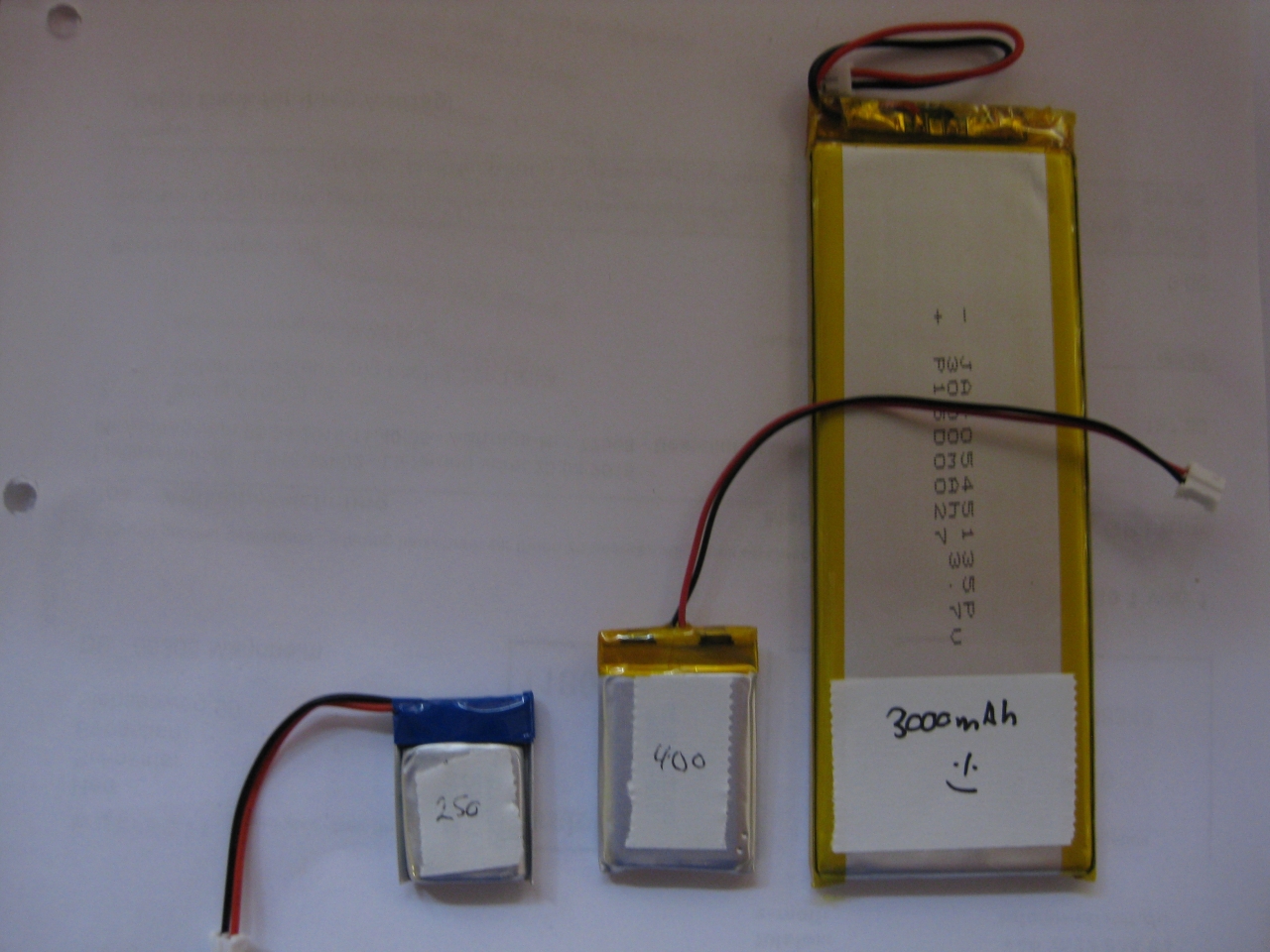
Here I used my Led modded NeoGeo Controller and put all together. Because of the Leds and more need of current. I used a bigger LiPo. The future will tell how long it works.
I am in search for a nice Harddisc Case in white, but I didn’t find any nice looking case…
After this I decided to put a 3,5Zoll Sata Harddisc into a broken Wii.
I am planing to use the original Power Supply and the original USB Connectors.
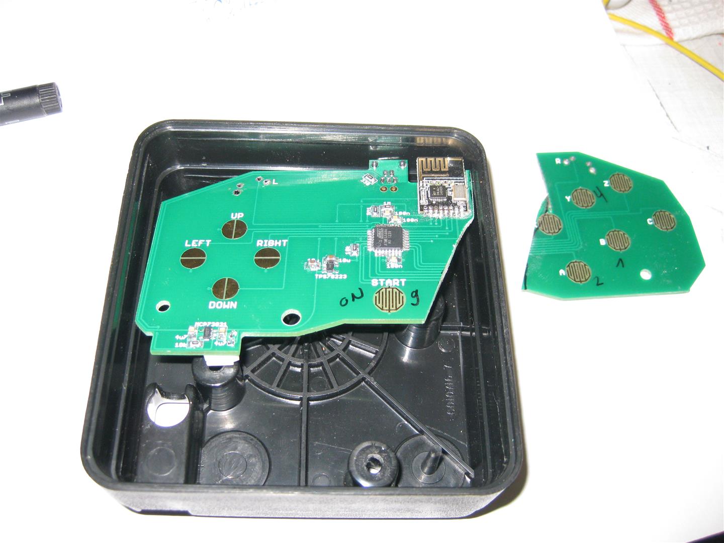
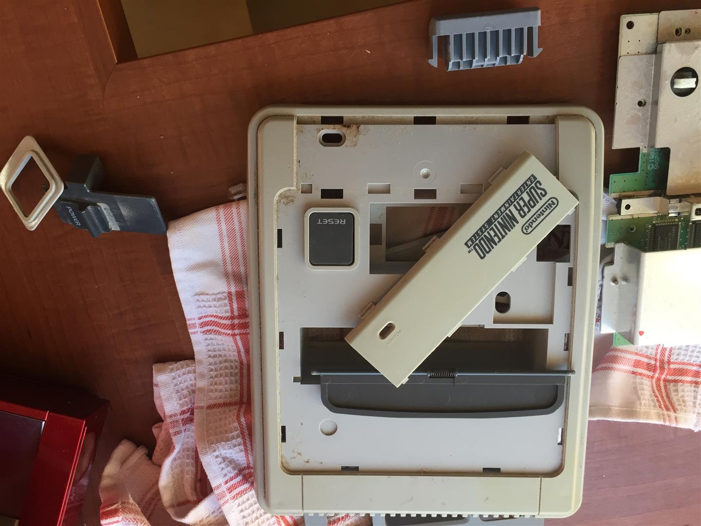
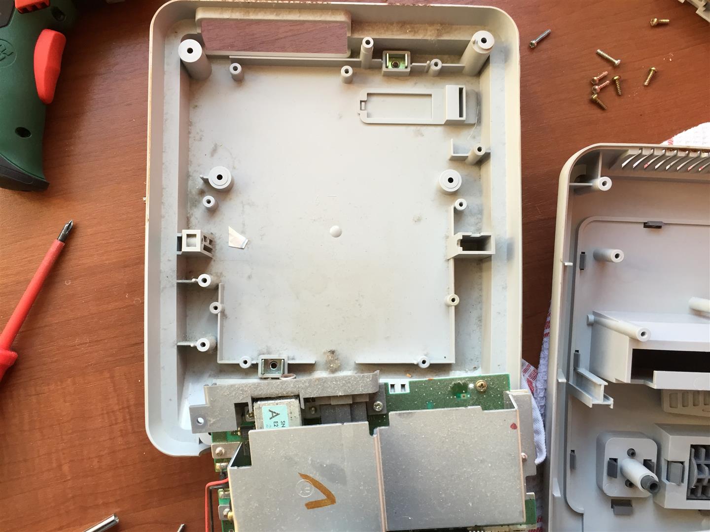
I opened the wii and removed all until you only have the main PCB inside
I removed to parts (red marked) to disable the USB Wires into the mainboard and connected the USB Cables from the USB/Sata Connector to the onbaord USB Port
The power is taken from the Top Site of the mainbaord. Here I have to remove the original Fuse (red marked) to avoid getting any voltage to the mainboard.
You can get 12V to power up harddisc from the right site of the fuse.
GND is found at the edge of the mainboard.
I placed a standard 7805 voltage regulator to get the 5V for the Harddisc
Here you can see original case of the used USB/Sata Connector
all together
I extended the power Led of the USB/Sata Adapter to the original power LED of the wii
And here you can see the final backsite with connectors
For changing the Volume of a pinball you always have to open the coindoor.
And mostly you have the key in the coindoor.
I find a solution to move the switches outsite of the coindoor.
So you can remove the key and it looks better.
I connected the volume + and volume – parallel to the switches inside of the coindoor.
But they don’t work without opening the door.
So I have to put a „coin-open“ switch outsite too. Its the green one.
To change the volume you have to press the green once and then you can change the volume via the two red and black switches as usual.
Here the first pics
Video:
you have only to replace the original red plastic with two screws
remove the lamp
,
put in the new one with the wires
connect the three crocodiles to the inside switches
here you can see the replaced coindoor plastic with the new one


 ,
,


")
")
")
")
")
")
")


